Double frequency combiner

a technology of double frequency and combiner, which is applied in the direction of multi-frequency-changing modulation transference, multi-frequency division multiplex, multiplex communication, etc., can solve the problems of difficult control of dielectric substrate material during batch production, large bulkage, and low power capacity, so as to improve the structure of the invention, reduce the loss of differentially, and the effect of large power capacity

Active Publication Date: 2010-11-04
COMBA TELECOM TECH (GUANGZHOU) CO LTD
View PDF6 Cites 26 Cited by
  • Summary
  • Abstract
  • Description
  • Claims
  • Application Information

AI Technical Summary

Benefits of technology

[0018]Compared with prior art, the invention can obtain the following advantages. The 2G / 3G dual frequency multiplexer of the invention is implemented by a plurality of coaxial harmonic oscillator type band pass filters. By this way, the direct current circuit and the RF circuit are isolated from each other. Utilization of distributed blocking capacitors makes the product of the invention small. Moreover, improvement of the structure of the invention brings effect such as less differential loss, large power capacity, as well as high isolation degree between circuits.

Problems solved by technology

The disadvantages of product of this type include large bulkage and low power capacity.
Moreover, inactive inter-modulation is greatly depended on property of dielectric substrate material and therefore, it is difficult to control the dielectric substrate material during batch production.

Method used


Image

  • Double frequency combiner
  • Double frequency combiner
  • Double frequency combiner

Examples


Embodiment Construction

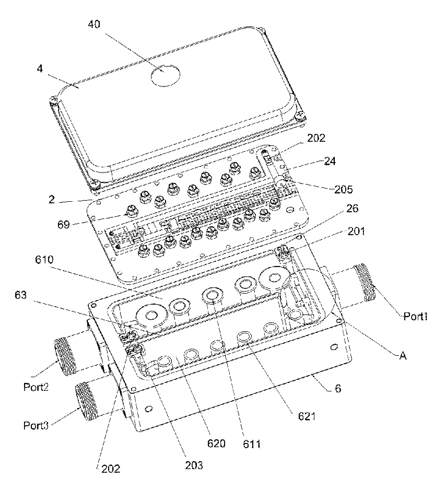
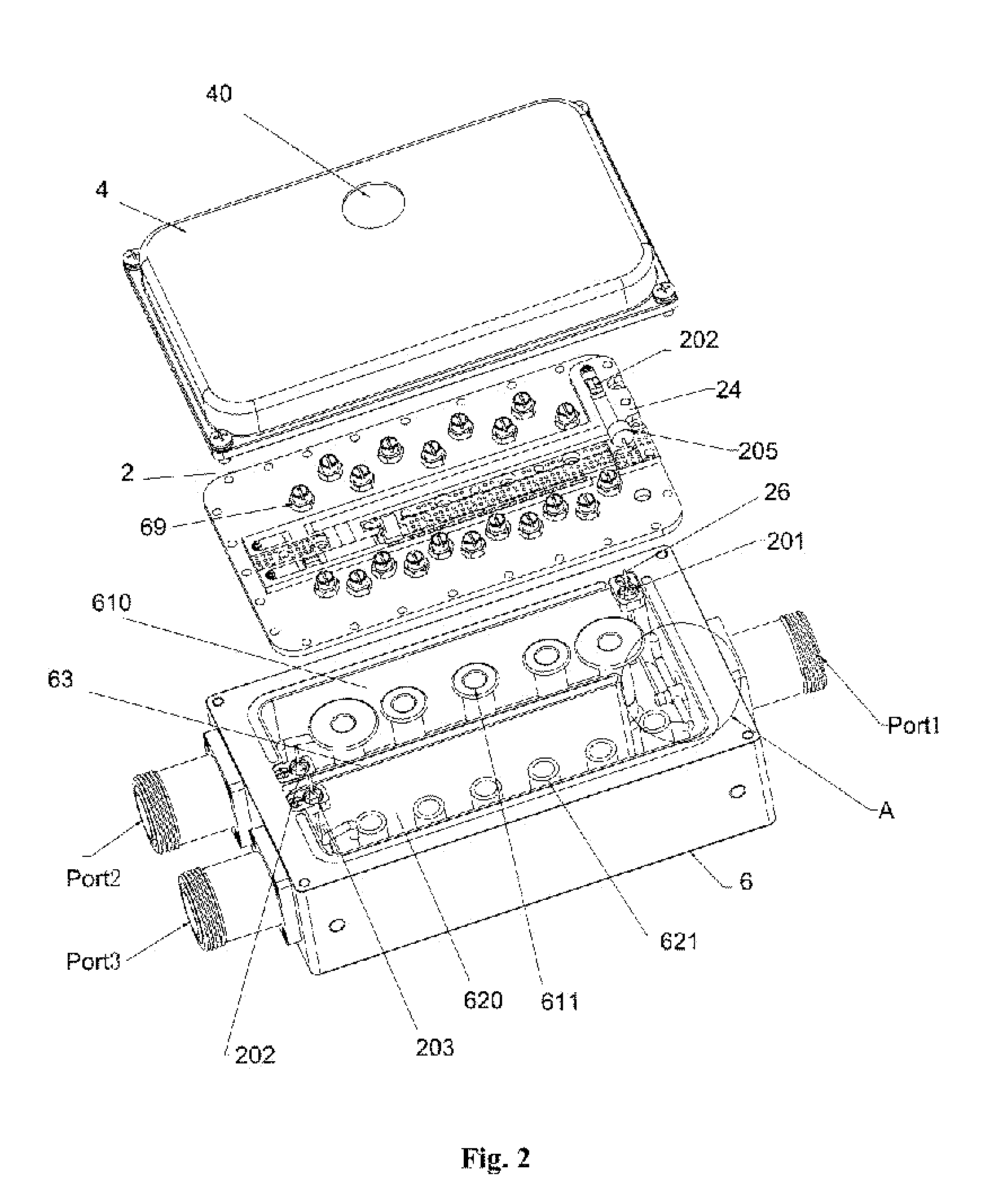
[0025]With reference to FIG. 2, a dual frequency multiplexer of the invention is shown, which is used mainly to multiplex 2G and 3g signals.

[0026]As shown in FIG. 2, the multiplexer is of a box type, and is constructed by a base body 6, a cover plate 2 and a cover body 4 collectively.

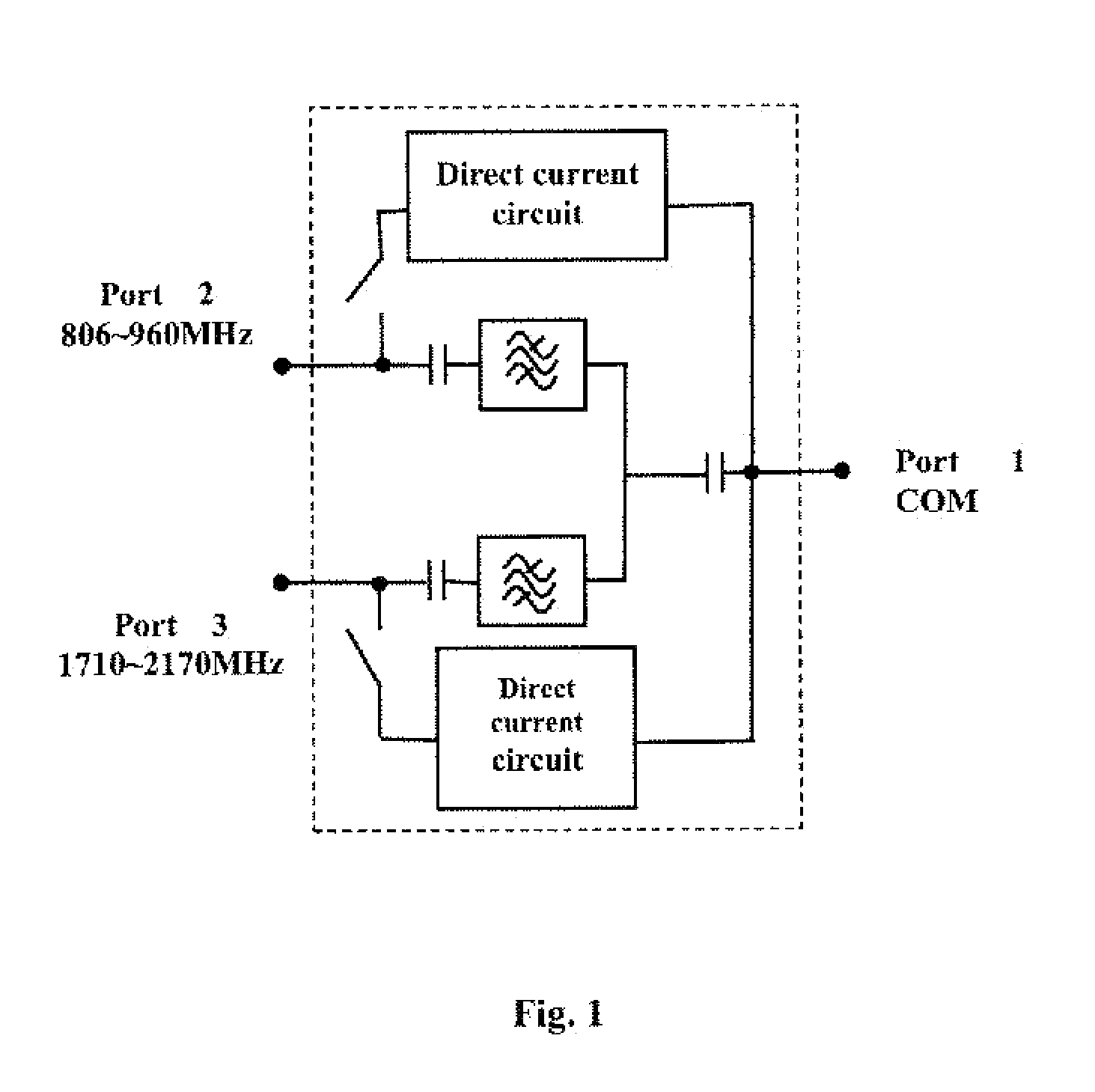
[0027]A first port Port2 and a second port Port3 are provided at left side of the base body 6, both of which are adapted to receive radio frequency (RF) signals with frequency of 806-960 MHz and 1710-2170 MHz respectively. A multiplexer port Port1 is located at the right side of the base body 6. The multiplexer port Port1 is able to output RF signal multiplexed by the first and second ports (Port2 and Port3). Alternatively, an input signal can be de-multiplexed through the first and second ports (Port2 and Port3).

[0028]Two RF circuits, that is, a first RF circuit and a second RF circuit are integrated in the base body 6. The first RF circuit is consisted of the first port Port2, a blocking capacitors (n...


PUM


Abstract

The invention discloses a dual frequency multiplexer by which a first and second coaxial harmonic oscillator type band pass filters are disposed in a box. The box includes a base body, a cover plate and a cover body. The two coaxial harmonic oscillator type hand pass filters are located on the base body and spaced each other by a metal plate; the multiplexer port, first and second ports are positioned on lateral side of the base body. The blocking capacitors are contained in the coaxial chamber of the two coaxial harmonic oscillator type band pass filters. The cover plate is secured on the base body; the first and second direct current circuits are placed on the cover plate; the low pass filters of the first and second direct current circuits are fixed on an edge of a top surface of the coaxial chamber by means of a support member; the cover body and the base body are fastened with each other. The blocking capacitors each are of distributed parameter capacitor. Utilization of distributed blocking capacitors makes the product of the invention small. Moreover, improvement of the structure of the invention brings effect such as less differential loss, large power capacity, as well as high isolation degree between circuits.

Description

FIELD OF THE INVENTION[0001]The invention relates to a processing device for multiplexing between the second generation and third generation communication systems, and more particularly relates to dual frequency multiplexer.BACKGROUND OF THE INVENTION[0002]With rapid development of mobile communications, a scheme in which multiple systems share a common station as well as a common antenna feeder resource has gotten its population by more and more operators. By this way, advantage of sharing resource and reducing system device cost can be obtained. Within a system in which 2G / 3G sharing a common antenna feeder, dual frequency multiplexer is a necessary microwave component that mainly serves to multiplex / de-multiplex signals of different systems so as to save the length of feed cable, simplify system construction and reduce cost. In addition, power is supplied to the devices at base station tower via a radio frequency cable and accordingly, the multiplexer connected with the feed cabl...

Claims


Application Information

Patent Timeline
Patent Type & Authority Applications(United States)
IPC IPC(8): H04J1/00
CPCH01P1/2136
Inventor DI, YINGJIEHE, TAOHE, BINSHU, MENGMENGHUANG, JINGMIN
Owner COMBA TELECOM TECH (GUANGZHOU) CO LTD
Why Eureka
Try Eureka