Passive Electro-Optical Tracker

a tracking device and electro-optical technology, applied in the field of passive electro-optical tracking devices, can solve the problems of reducing the computing power needed to track hostile projectiles, and achieve the effects of saving lives, short reaction time, and high degree of accuracy

Inactive Publication Date: 2010-11-04
LIGHT PRESCRIPTIONS INNOVATORS
View PDF42 Cites 35 Cited by
  • Summary
  • Abstract
  • Description
  • Claims
  • Application Information

AI Technical Summary

Benefits of technology

[0007]The temperature of fast moving projectiles depends directly on their speed [1]. According to Wien's displacement law, the spectrum maximum of light emitted by a heated body shifts to shorter wavelengths as the temperature increases [4]. The atmosphere has two high transmission windows in the MWIR region, at wavelengths from 3.0 to 4.2 μm and from 4.3 to 5.2 μm. The temperature of an object can be estimated by comparing the irradiance measured by the sensor for that object for these two sub-wavebands. Once this value is determined the speed of the projectile can then be calculated. The instantaneous speed data and array of azimuth and elevation obtained from the electro-optical sensor, together with the calibrated signal levels in each of its pixels, can be used to determine the ballistic trajectory by a proprietary application of the least-square method. This approach can determine the 3D trajectory of projectiles with very high degree of accuracy using passive electro-optical sensors without the need for scanning lidar.
[0008]The imaging system can be a fixed staring array that monitors the entire target region for every image cycle. This staring array may use a “fish-eye” or similar lens or mirror arrangement to view 360° of azimuth using a CCD or other sensor array on a flat image plane. The projectile tracking optics can be compact as 60 mm in diameter and no more than 100 mm in length, and can be mounted on an army vehicle or unmanned aerial vehicle (UAV) to support troops with tactical battlefield information. This passive electro-optical tracker can have a short enough reaction time not only to back-track projectiles and pinpoint the source of the fire nearly in real time, but also to trigger alarms and automatic countermeasures. The system can also be tied into a battlefield database to help distinguish friendly versus enemy fire, which can also be used to both save lives and quickly rule out projectiles which are not emanating from hostile positions. The latter can reduce the computing power needed to track hostile projectiles.
[0009]One objective of the present invention is to make possible a system reaction time short enough to backtrack projectiles and pinpoint the source of the fire to trigger automatic countermeasures, such as laser designation or even counter-sniper fire, before a second enemy shot can be fired. Also, an audible warning to troops in the target zone could allow a second or two of time to simply duck.

Problems solved by technology

The latter can reduce the computing power needed to track hostile projectiles.

Method used


Image

  • Passive Electro-Optical Tracker
  • Passive Electro-Optical Tracker
  • Passive Electro-Optical Tracker

Examples


Embodiment Construction

[0028]A better understanding of various features and advantages of the present methods and devices may be obtained by reference to the following detailed description of the invention and accompanying drawings, which set forth illustrative embodiments. Although these drawings depict embodiments of the contemplated methods and devices, they should not be construed as foreclosing alternative or equivalent embodiments apparent to those of ordinary skill in the subject art.

1. Principles of Operation

1.1 Aerodynamics of Fast Moving Projectiles; Speed-Temperature Dependence.

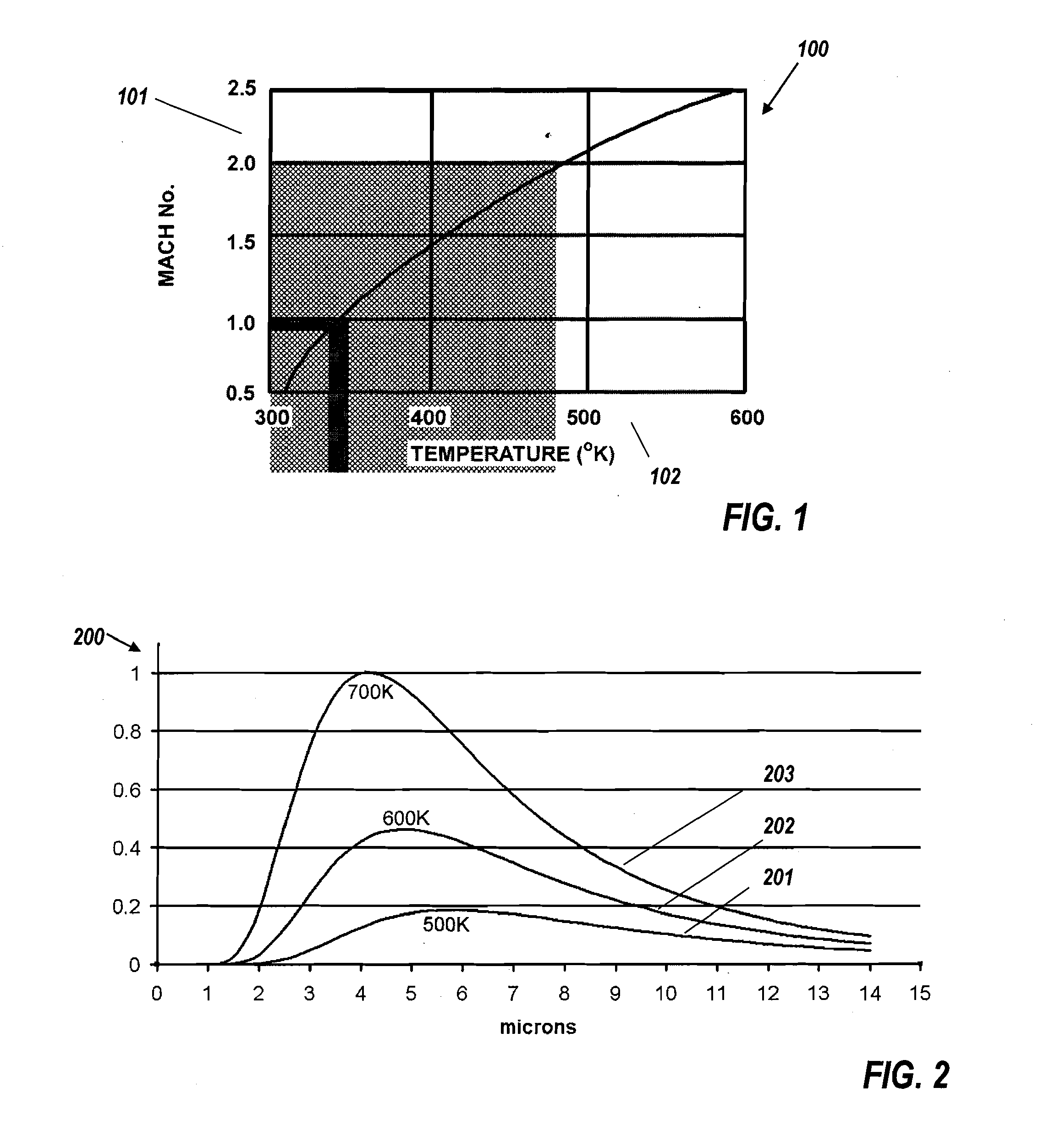
[0029]The surface of fast-moving bullets and other projectiles is quickly heated by air friction to a speed-dependent temperature, as detailed in Ref [1]. FIG. 1 shows a graph 100 with an ordinate 101 of projectile speed in Mach numbers (relative to Mach 1=340.3 m / s) and an abscissa 102 of absolute temperature. High speed IR imaging of an example of a bullet from a rifle reveals that it is traveling with a speed of 840 m...


PUM


Abstract

A passive electro-optical tracker uses a two-band IR intensity ratio to discriminate high-speed projectiles and obtain a speed estimate from their temperature, as well as determining the trajectory back to the source of fire. In an omnidirectional system a hemispheric imager with an MWIR spectrum splitter forms two CCD images of the environment. Three methods are given to determine the azimuth and range of a projectile, one for clear atmospheric conditions and two for nonhomogeneous atmospheric conditions. The first approach uses the relative intensity of the image of the projectile on the pixels of a CCD camera to determine the azimuthal angle of trajectory with respect to the ground, and its range. The second calculates this angle using a different algorithm. The third uses a least squares optimization over multiple frames based on a triangle representation of the smeared image to yield a real-time trajectory estimate.

Description

CROSS REFERENCE TO RELATED APPLICATIONS[0001]This application claims benefit of co-pending and commonly owned U.S. Provisional Patent Applications No. 61 / 208,700 titled “Multiple Object Omnidirectional Passive Electro-Optical Tracker” filed Feb. 25, 2009 by Agurok and No. 61 / 260,149 titled “Passive Electro-Optical Tracker” filed Nov. 11, 2009 by Agurok. Both of those applications, which have at least one common inventor to the present application, are incorporated herein by reference in their entirety.BACKGROUND OF THE INVENTION[0002]Surveillance, detection, and tracking of multiple high-speed objects, particularly bullets, mortars, small rockets, and artillery shells, can help military forces immediately locate sources of enemy fire and trigger countermeasures, thereby reducing combat casualties.[0003]The traditional techniques for detection and tracing of fast moving objects are different kinds of radar but unfortunately, traditional radar has inherently low resolution for such sm...

Claims


Application Information

Patent Timeline
Patent Type & Authority Applications(United States)
IPC IPC(8): G06K9/00
CPCF41H13/00G01J5/60G01J2005/0077G01P5/10G01S5/16G06T2207/30241G06K2009/3291G06T7/20G06T2207/10048G06T2207/30212G01S11/12G06V10/62
Inventor AGUROK, ILYAFALICOFF, WAQIDIALVAREZ, ROBERTO
Owner LIGHT PRESCRIPTIONS INNOVATORS
Why Eureka
Try Eureka