Bellows type dispensing tip, bellows type dispensing apparatus and method of bellows type dispensing processing
a technology of bellows type and bellows type, which is applied in the direction of laboratory glassware, instruments, transportation and packaging, etc., can solve the problems of large apparatus, inability to perform simultaneous processing using a number of droppers, and high product quality management requirements, so as to reduce the size of the apparatus, facilitate manufacturing, and simplify the structure of the apparatus
- Summary
- Abstract
- Description
- Claims
- Application Information
AI Technical Summary
Benefits of technology
Problems solved by technology
Method used
Image
Examples
first embodiment
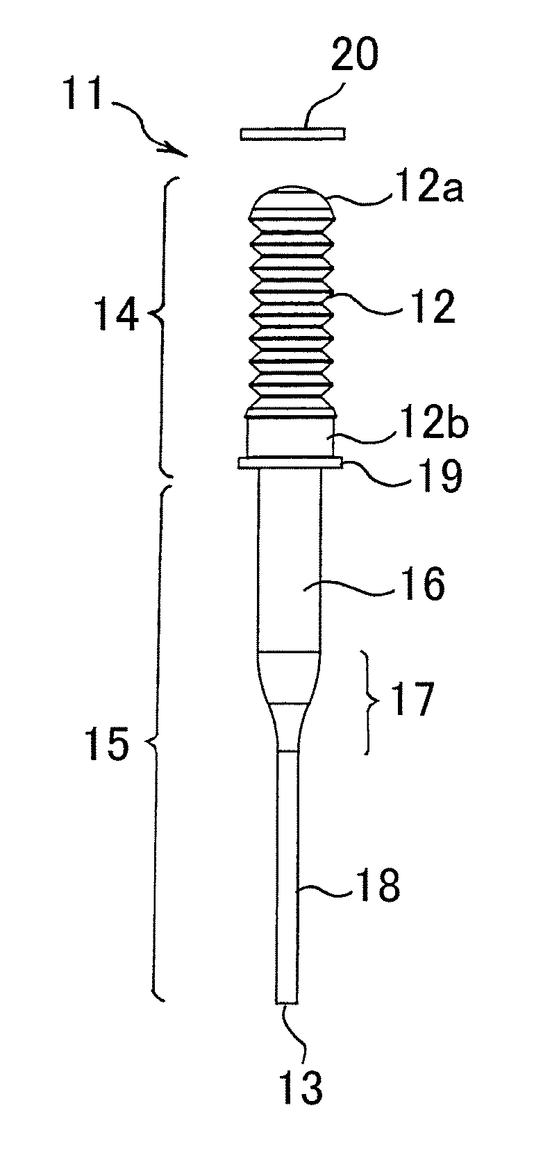
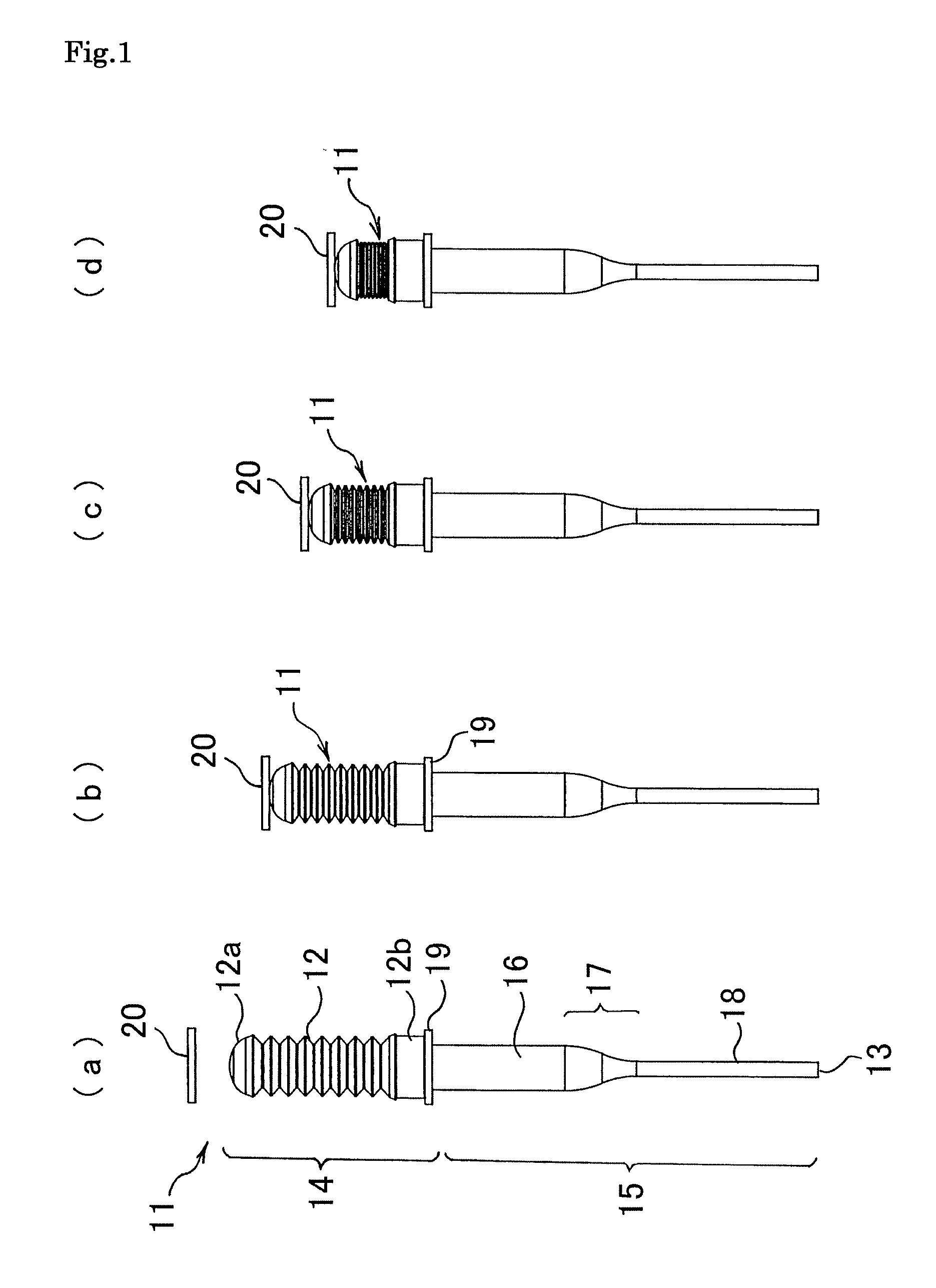
[0083]FIG. 1(a) conceptually shows a bellows type dispensing tip 11 according to the present invention being supported on a dispensing head 70 of a bellows type dispensing apparatus 10 described later. In the bellows type dispensing tip 11, there are provided: a substantially cylindrical shaped longitudinal accommodating section (14, 15) having an axis thereof along the vertical direction, that is capable of accommodating a liquid or gas within the interior thereof surrounded by a substantially cylindrical shaped wall face, and that has a bellows 12 serving as a deformable deforming wall face in a portion of the wall face; and an opening section 13 provided so as to surround the axis thereof at the bottom end of the accommodating section, that communicates with the accommodating section (14, 15) and that enables inflow and outflow therethrough of a liquid suctioned or discharged by deformation of the bellows 12.
[0084]The bellows 12 is deformably provided in a portion of the wall fac...
second embodiment
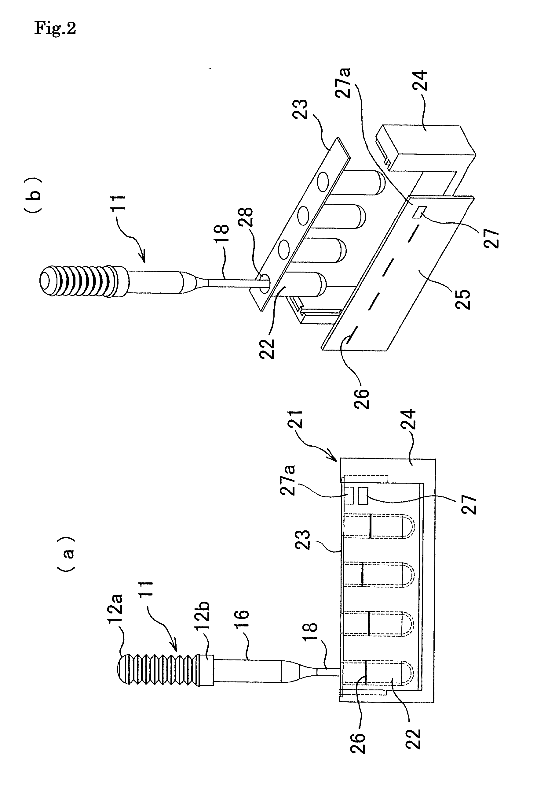
[0090]FIG. 2 shows an example of a cartridge container 21 suitable for the bellows type dispensing tip 11. FIG. 2 (a) is a side view showing a state where the thin tube section 18 of the bellows type dispensing tip 11 is inserted into a liquid accommodating section 22 of the cartridge container 21, and FIG. 2 (b) is an exploded perspective view of the cartridge container 21.
[0091]The cartridge container 21 is such that the top end of each of four of the liquid accommodating sections 22 is attached to a region around each of four holes 28 provided in an upper plate 23, and each liquid accommodating section 22 projects downward from the lower side of the upper plate 23. The upper plate 23 is horizontally mounted on the upper side of a channel shaped container supporting frame 24, and two transparent gauging side plates 25 are fitted on both sides of the container supporting frame 24. In positions on the gauging side plate 25 corresponding to the respective liquid accommodating sectio...
third embodiment
[0092]Next, a bellows type dispensing apparatus 10 is described, with reference to FIG. 3 to FIG. 6.
[0093]FIG. 3 is a front view of the bellows type dispensing apparatus 10 according to the present embodiment. The bellows type dispensing apparatus 10 is such that on a stage 30, there are provided: a dispensing head 70 that supports six of the bellows type dispensing tips 11 for suctioning or discharging a liquid into or from each bellows type dispensing tip 11 by deforming the bellows 12 of the bellows type dispensing tip 11; a container set 31 having a plurality (six in this example) of reagent accommodating containers 32 capable of accommodating various kinds of liquids, reagents, specimens and the like; and a head moving section (44, 45, 46) for moving the dispensing head 70 with respect to the container set 31. Reference symbol 30a denotes a supporting member that supports the stage 30.
[0094]The dispensing head 70 serving as a tip supporting section that supports a series of si...
PUM
 Abstract
Description
Claims
Application Information
 - R&D
- Intellectual Property
- Life Sciences
- Materials
- Tech Scout
- Unparalleled Data Quality
- Higher Quality Content
- 60% Fewer Hallucinations
Browse by: Latest US Patents, China's latest patents, Technical Efficacy Thesaurus, Application Domain, Technology Topic, Popular Technical Reports.
© 2025 PatSnap. All rights reserved.Legal|Privacy policy|Modern Slavery Act Transparency Statement|Sitemap|About US| Contact US: help@patsnap.com


