System and method for utility usage, monitoring and management

a utility and monitoring system technology, applied in the field of utility monitoring and management, can solve the problems of not being able to achieve cost-effective and systematic ways, difficult to quantify typical and easy ways for individuals to conserve resources, and high cost of serious conservation efforts (such as solar energy conversions)

Active Publication Date: 2010-11-04
THINKECO
View PDF6 Cites 84 Cited by
  • Summary
  • Abstract
  • Description
  • Claims
  • Application Information

AI Technical Summary

Benefits of technology

[0010]It is a more particular object of the invention to be able to reliably identify the plurality of appliances that are plugged into respective multi-port outlet monitoring devices (OMDs) that may be found in a residential or commercial setting.
[0011]As a method of remotely identifying at least one unknown appliance, one embodiment of the invention includes at least the operations of independently metering waveform data transmitted from said at least one unknown appliance via a multi-port monitoring device over an elapsed time period; wirelessly transmitting the independently metered waveform data from the multi-port monitoring device to a co-located system controller; constructing one or more appliance signatures at said co-located system controller for the at least one unknown appliance from the wirelessly transmitted waveform data; and processing the one or more constructed appliance signatures at the system controller to identify the at least one unknown appliance.
[0012]As a system for reliably identifying a plurality of appliances that are plugged into respective multi-port outlet monitoring device, one embodiment of the invention includes at least: An identification and detection system for detecting and identifying a plurality of unknown electrical devices, comprising: (I) a local system controller 50 as shown in FIG. 1C, comprising: (i) a data uploading module 52 configured to send appliance signature data from the local system controller 50 to the system management node 102; (ii) a data packaging module 54 operatively coupled to the data uploading module 52 and configured to compress appliance signature data for transmission over a network 60; (iii) a database 56 configured to store a local copy of canonical signatures; (iv) a processor 58 configured to run one or more software modules that perform key algorithmic steps as flowcharted in FIGS. 2-7; (v) a module 67 configured to wirelessly receive independently metered waveform data; (II) a plurality of multi-port monitoring devices 12 configured to independently meter waveform data transmitted from a respective plurality of unknown appliances over an elapsed time period and wirelessly transmit the waveform data to the system controller 50, as shown in FIG. 1B; (III) a system management node 102 as shown in FIG. 1A comprising: (i) a gateway computer 104 configured to buffer the independently metered waveform data received from the plurality of multi-port monitoring devices and perform server load balancing; (ii) a processor 114 configured to provide dedicated access to an archival database 116; (iii) a plurality of distributed computing nodes 112 configured to execute computational instructions pertaining to the management of canonical signatures and general appliance detection related tasks; (iv) a cluster front end 106 configured to load distribute, load balance, as well as generally manage the distributed computing nodes 112; (v) a transient database 110 for storing short- to mid-term data related to appliance detection.
[0013]As a computer readable medium including at least computer program code for enabling a consumer to intelligently manage the consumption of energy by multiple users and / or multiple loads within a residential or commercial setting, one embodiment of the invention includes at least computer program code for: independently metering waveform data from said at least one unknown appliance via a multi-port monitoring device over an elapsed time period; wirelessly transmitting the independently metered waveform data from the multi-port monitoring device to a co-located system controller; constructing one or more appliance signatures at said co-located system controller for the at least one unknown appliance from the wirelessly transmitted waveform data; and processing the one or more constructed appliance signatures at the system controller to identify the at least one unknown appliance.

Problems solved by technology

Unfortunately, there are no cost-effective and systematic ways today to convert this desire into a rigorous, measurable conservation effort.
On one hand, typical and easy ways for individuals to conserve resources are very hard to quantify (e.g., taking shorter showers).
On the other, serious conservation efforts (such as solar energy conversions) are very expensive and require significant lifestyle changes.
Furthermore, when consumers do try to conserve, they are unable to see the impact of their collective efforts.

Method used


Image

  • System and method for utility usage, monitoring and management
  • System and method for utility usage, monitoring and management
  • System and method for utility usage, monitoring and management

Examples


embodiment

Section III. Exemplary Residential Embodiment

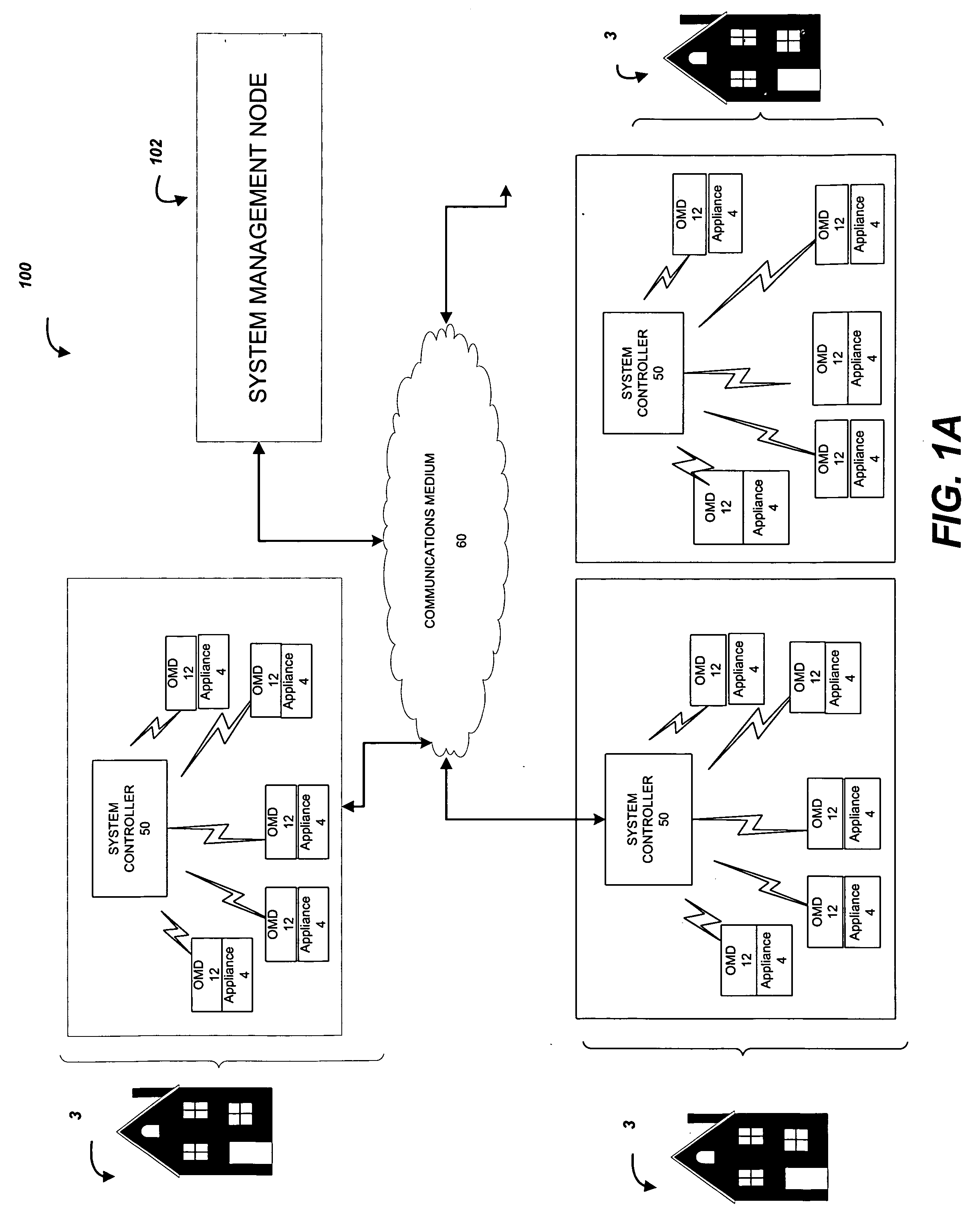
[0087]With reference again to FIG. 1C, details of the system controller 50 are shown to illustrate an exemplary embodiment of the invention. As described herein and illustrated in the attendant figures, the appliance detection and identification system 100 utilizes a system controller 50 situated inside a client node 3 that can be, in one embodiment, a typical residence setting, including, without limitation, a single family residence or a multiple family residence, such as an apartment building. However, it should be understood that the invention has much broader applicability. In particular, it should be understood by those skilled in the art and guided by the teachings provided herein that the appliance detection and identification system 100 may be used in other suitable settings, including, for example, commercial, industrial and utility applications. Other suitable settings are apparent to the reader.

[0088]With continued reference t...


PUM


Abstract

Systems and methods are provided for collecting waveform data for a plurality of appliances that may be found in a residential or commercial setting using multi-port outlet monitoring devices to obtain power consumption profiles that indicate power consumption on a per-appliance and/or per-location basis and/or per user basis. The plurality of appliances is reliably identified from the power consumption profiles. In accordance with a method embodiment, waveform data transmitted from an unknown appliance is independently metered via a multi-port monitoring device over an elapsed time period. The metered waveform data is wirelessly transmitted from the multi-port monitoring device to a co-located system controller which constructs an appliance signature. The process may be repeated to generate multiple appliance signatures. The one or more appliance signatures are compared to a database of pre-stored canonical signatures to determine if there is a match to identify the appliance.

Description

BACKGROUND OF THE INVENTION[0001]1. Field of the Invention[0002]The present invention generally relates to methods and systems for utility usage, monitoring and management.[0003]2. Description of the Related Art[0004]With serious concerns regarding global warming on the rise, civic and corporate efforts to improve energy conservation have steadily increased. Major US cities, for example, have independently vowed to reduce their emissions level to 7% below 1990 levels by 2012. New developers, perhaps in response to rising market and civic pressures, have started to adhere to standards set by the US Green Building Council's Leadership in Energy and Environmental Design (LEED) program. Finally, many corporations are initiating green corporate energy marketing campaigns and increasing green product lines wherever possible.[0005]In response to increasing media coverage of global warming, the average consumer's desire to reduce carbon emissions is at an all-time high, with 61% of the popu...

Claims


Application Information

Patent Timeline
Patent Type & Authority Applications(United States)
IPC IPC(8): G06F15/18G06N5/04G06N5/02
CPCH02J13/0079Y04S20/38Y04S20/221Y02B70/3216H02J2310/70H02J2310/12H02J13/00004H02J13/00028Y02B70/30Y04S20/222Y02B70/3225G01D2204/24H02J13/00022H02J13/00002Y04S40/126Y02E60/00Y02B90/20Y04S20/30
Inventor SHIMADA, JUNSHIBATA, MEIMACMENAMIN, PHILIP EOIN
Owner THINKECO
Why Eureka
Try Eureka