
Digital Broadcasting System and Error Correction Method Thereof

a digital broadcast receiver and error correction technology, applied in the field of digital broadcast receivers, can solve the problems of cable transmissions experiencing similar problems with signal interference, terrestrial and satellite radio transmissions are very susceptible to signal distortion, and digital broadcast receivers demodulating bits incorrectly from the received analog signal, so as to improve the chances of recovering complete messages

Active Publication Date: 2010-11-04
LIU YANG
View PDF6 Cites 12 Cited by
  • Summary
  • Abstract
  • Description
  • Claims
  • Application Information

AI Technical Summary

Benefits of technology

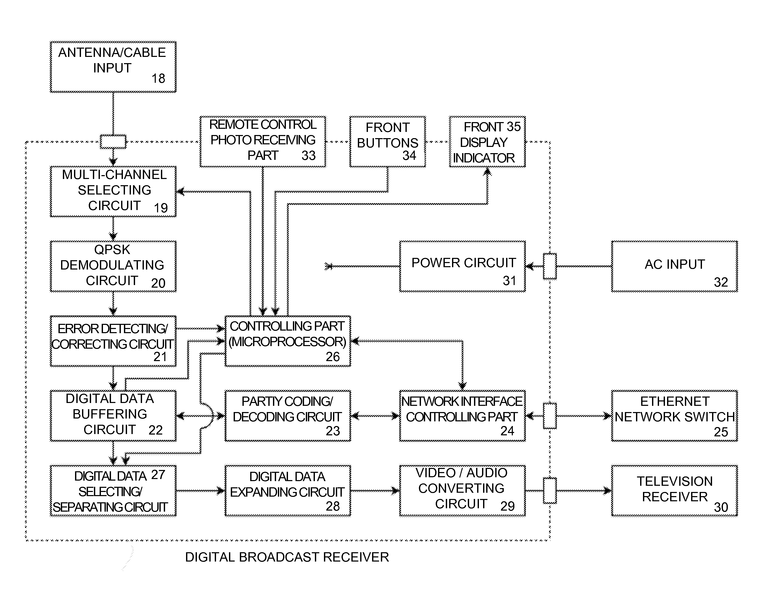
[0010]It is an object of the present invention to provide a digital broadcast receiver that creates, transmits, receives, and decodes digital messages routed across a switched network, to compensate for independent bit errors in local receptions of a digital broadcast.
[0039]In the tenth embodiment of the present invention, the digital broadcast receivers are configured to intercept digital messages from a private radio / satellite communication link. In most cases, the messages are encrypted and cannot be decrypted if some pieces of the messages were received with error. Since the digital broadcast receivers are not participants in the communication network, they cannot request retransmission of the missing pieces. Thus, deploying an array of digital broadcast receivers to eavesdrop in the communication network will significantly improve the chances of recovering complete messages.

Problems solved by technology

Terrestrial and satellite radio transmissions, however, are very susceptible to signal distortions caused by local physical effects such as attenuation, cross-talk, and dynamic multipath interference.
Cable transmissions may also experience similar problems with signal interference; especially cross-talk induced by magnetic fields from unshielded conductors.
These distortions cause digital broadcast receivers to demodulate bits incorrectly from the received analog signal.
If uncorrected, single bit errors become significantly magnified when the digital signal is decoded and decompressed.
Unfortunately, in a digital broadcast, the data is communicated only in one direction (from broadcast station to receivers) and receivers cannot request retransmissions of the original data when they encounter errors.
Unfortunately, forward error correction fail sometimes and receivers with more errors than parity data cannot correct any of the errors.
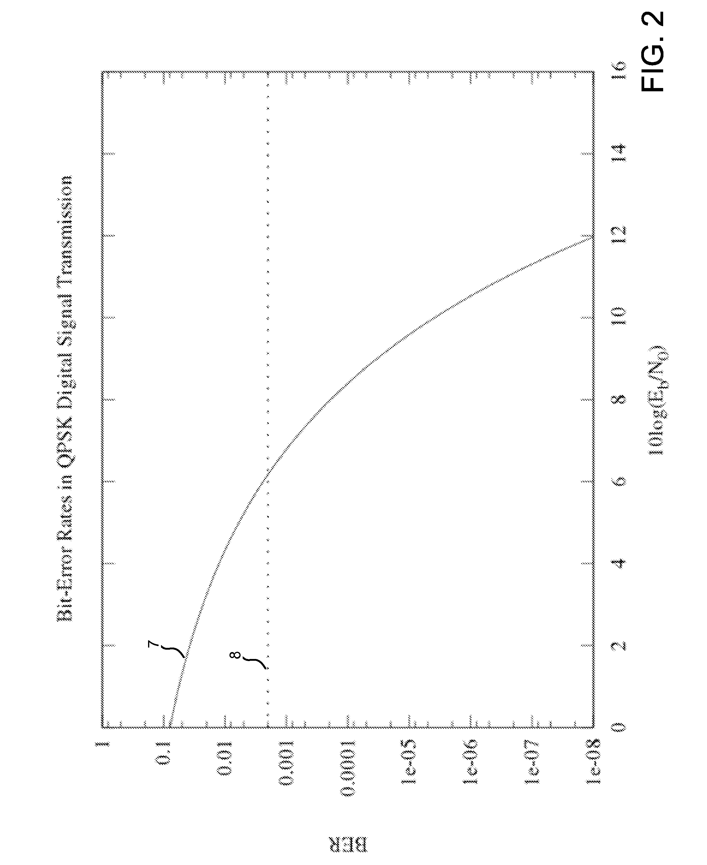
However, a large sustained bit-error rate may preclude many blocks from being decoded and completely interrupt the digital signal reception.
Thus, the coverage area of a digital broadcast is effectively limited by the average bit-error rate encountered at local receivers.
Unfortunately, these approaches are very costly to implement and do not scale well.
Broadcasting with more parity data enables reception at lower SNRs and can extend the broadcast range, but the extra parity data reduces the effective bandwidth of the transmission channel.
Finally, building repeater transmission towers involves significant cost, planning, and maintenance, and their proliferation may lead to further signal interference.

Method used


Image

  • Digital Broadcasting System and Error Correction Method Thereof
  • Digital Broadcasting System and Error Correction Method Thereof
  • Digital Broadcasting System and Error Correction Method Thereof

Examples


Embodiment Construction

[0051]The preferred embodiments of the present invention will be described below with reference to the appended drawings.

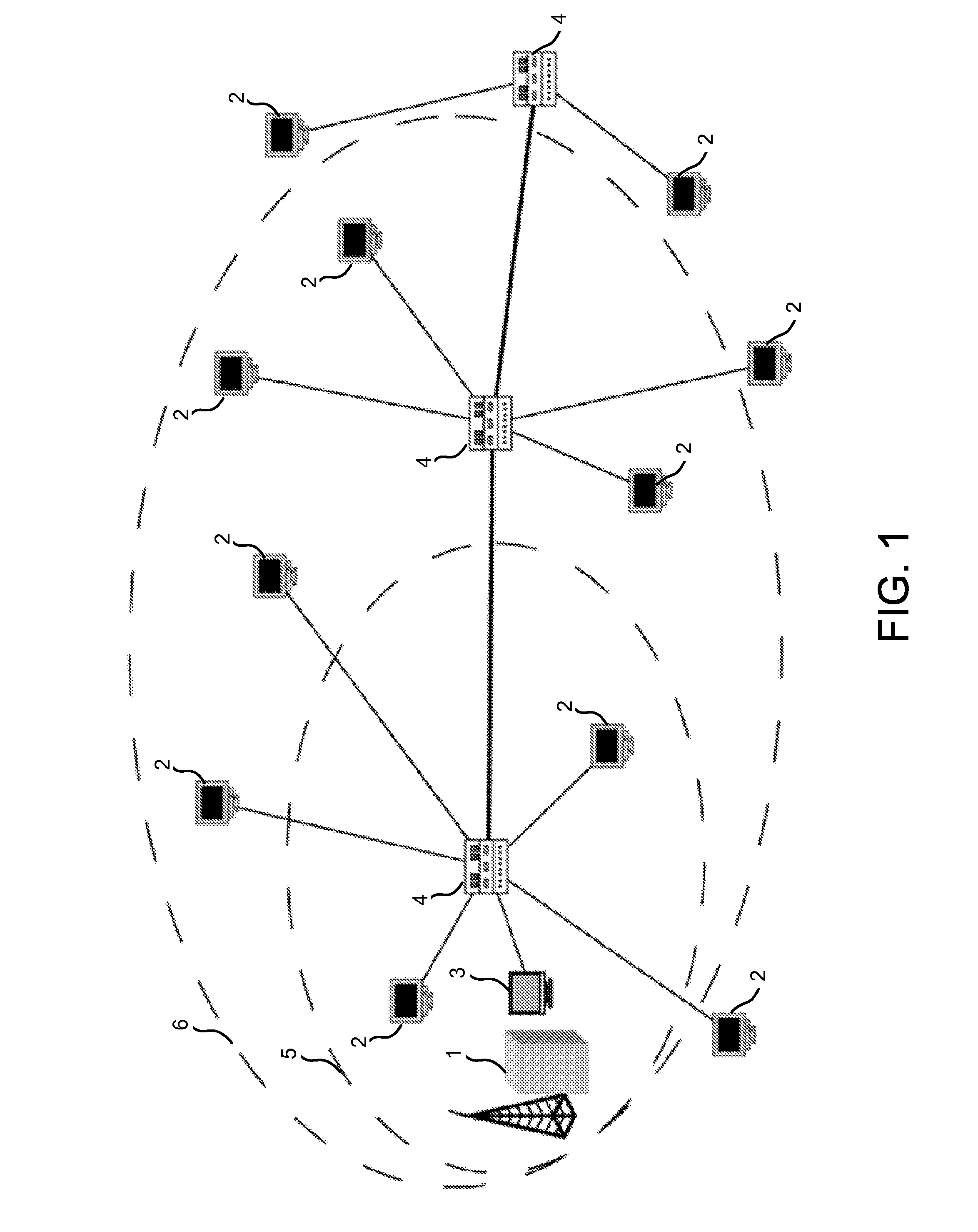
[0052]FIG. 1 shows the concept of the digital broadcasting system as a block diagram. This digital broadcasting system comprise a digital broadcasting station 1, a set of digital broadcasting receivers 2, a special “tracker”3, and a set of switched network routers 4.

[0053]A program produced by the digital broadcasting station consists of video and audio signals, which are coded into a digital signal and then compressed by a data compression technique. The compressed digital signal modulates a frequency band of an analog carrier signal, which is then broadcasted over-the-air by radio transmission. The analog signal is received by a digital broadcast receiver, which demodulates the analog signal into a compressed digital signal format and decodes from it the original video and audio signals. However, the analog signal may be distorted by noise, causing the digital s...


PUM


Abstract

A digital broadcasting system comprising of a digital broadcasting station, a set of digital broadcast receivers, and a switched network, wherein the digital broadcasting station transmits a digital signal to the set of digital broadcast receivers, and the digital broadcast receivers exchange error correction information with each other using the network to compensate errors in local receptions of the digital signal at each digital broadcast receiver location.

Description

BACKGROUND OF THE INVENTION[0001]1. Field of the Invention[0002]This invention relates generally to digital broadcasting. More particularly, it relates to a digital broadcast receiver which is used for a digital broadcasting system in which on the transmission side a broadcast station codes a digital signal to modulate an analog carrier signal for broadcast by radio or by cable, and which on the reception side, a digital broadcast receiver digitally demodulates the received analog signal into a digital signal, detects and corrects errors, and decodes the resulting output back into the original digital signal.[0003]2. Description of the Related Art[0004]Digital signals are typically encoded into a variety of data compression formats to reduce their transmission bit-rate to fit within bandwidth limitations / allocations. Each coded digital signal is assigned a distinct channel that modulates the respective band of an analog carrier signal for broadcast by radio or cable. Terrestrial and...

Claims


Application Information

Patent Timeline
Patent Type & Authority Applications(United States)
IPC IPC(8): H03M13/00H04L27/06G06F11/00
CPCH03M13/11H03M13/15H03M13/1515H03M13/19H03M13/2957H04L2001/0097H03M13/41H04L1/0022H04L1/0045H04L1/20H04L2001/0093H03M13/3761
Inventor LIU, YANG
Owner LIU YANG
Learn More