Apparatus for flamer fuel pressure control

a technology of fuel pressure control and flamer, which is applied in the field of flamers, can solve the problems of chemical retention and environmental impact of chemicals, and the flamer of pivonka '835 is not suitable for sterilization purposes, and achieves the effect of greatly reducing the pressure of the fuel tank

Active Publication Date: 2010-11-11
FLAME ENG
View PDF13 Cites 1 Cited by
  • Summary
  • Abstract
  • Description
  • Claims
  • Application Information

AI Technical Summary

Benefits of technology

[0017]The fuel supply pressure control system of the present invention provides a way to keep the fuel tank pressure near a predetermined value even during heavy fuel usage. To effect this control, fuel feed is selected from the vaporous and liquid components of the fuel. When vapor is being drawn from the tank, an equal amount of liquid must boil off to replace the vapor removed, plus a small volume equal to the volume of liquid converted to vapor. In contrast, when liquid is drawn off the fuel tank, the volume of liquid is much smaller than the volume of the same mass of liquid, i.e. the volume of the liquid is much smaller that the volume of the vapor. So the volume of vapor that must boil off in the tank to maintain the fuel tank pressure is greatly reduced.

Problems solved by technology

As usual, the issue becomes that of chemical retention and the effect of the chemicals on the environment.
Because of its open-flame design, the flamer of Pivonka '835 is not suitable for sterilization purposes.
These flamers are not suitable for the large task of sterilizing large amounts of poultry litter or soil, etc. due to their small coverage and the weight that must be supported or drawn by the user.
However, during periods of heavy fuel usage, the pressure inside the tank may fluctuate due to finite times required for boiling off of the liquid into vapor and variations in temperature.
Flaming, then, regardless of the purpose, may suffer in quality as long as the tank pressure is permitted to vary.

Method used


Image

  • Apparatus for flamer fuel pressure control
  • Apparatus for flamer fuel pressure control
  • Apparatus for flamer fuel pressure control

Examples


Embodiment Construction

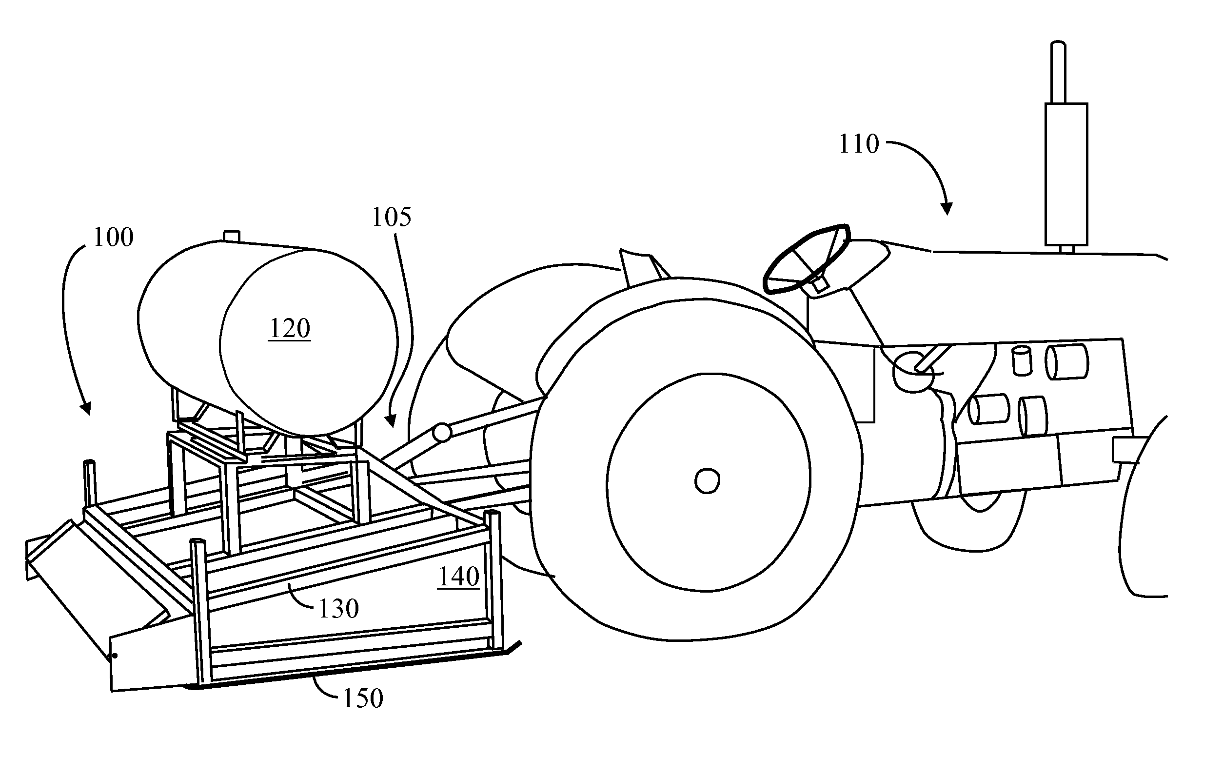
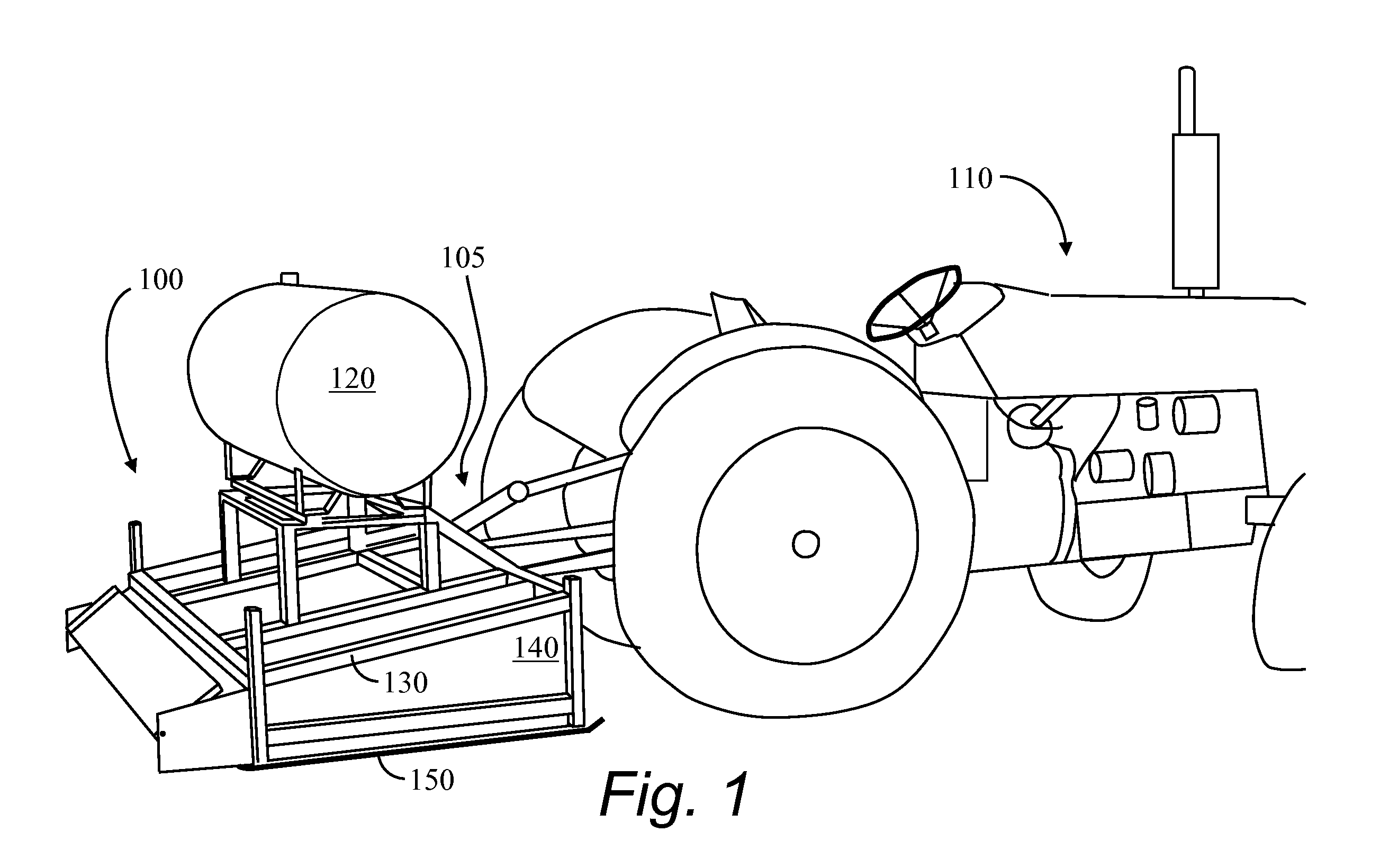
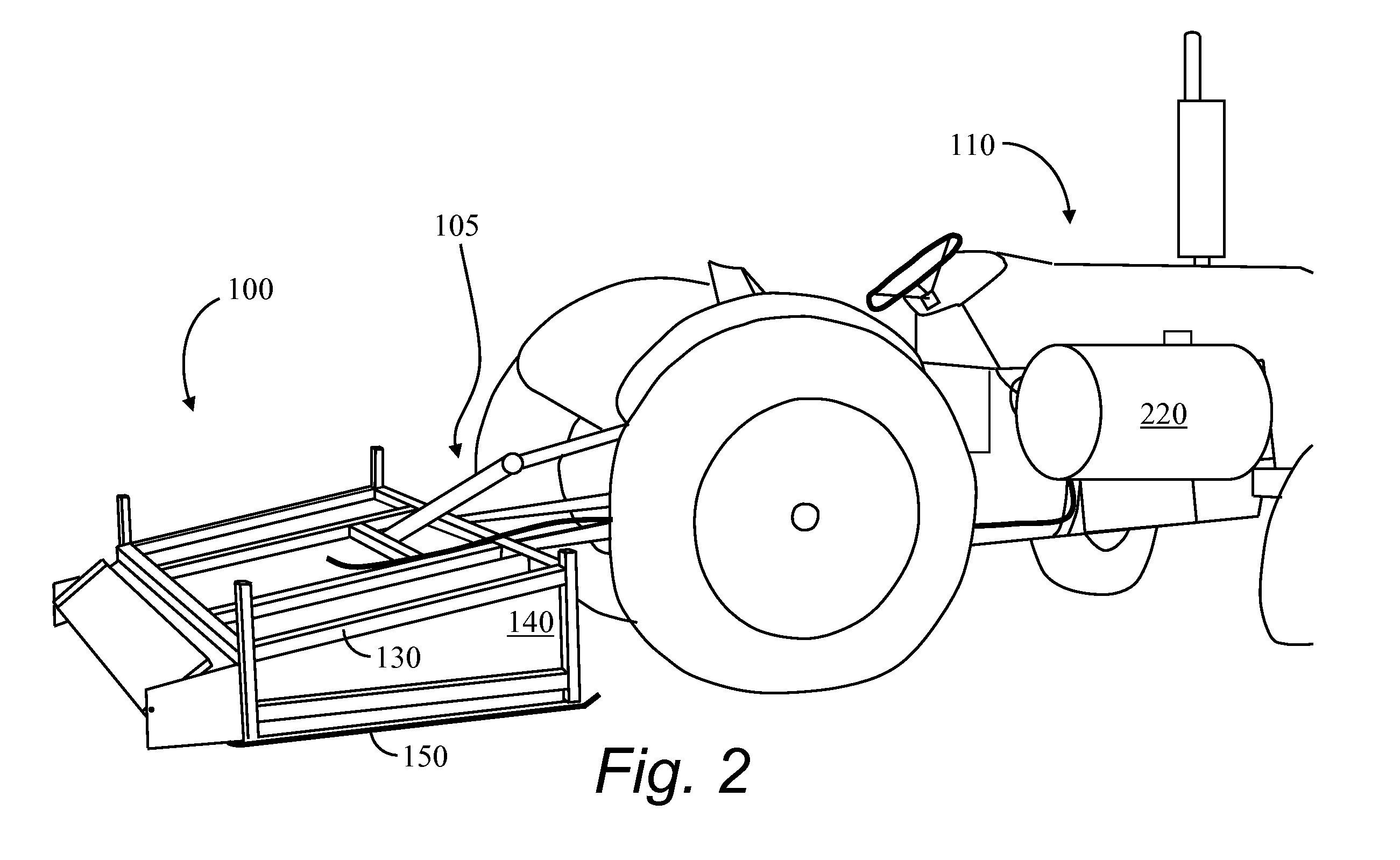
[0035]A perspective view of one embodiment of the present invention is shown in FIGS. 1 and 2. A side view and a rear view are seen in FIGS. 3 and 4, respectively. A mobile flamer 100 is shown mounted on an implement hitch 105 of a tractor 110. Fuel may, optionally, be carried on the flamer in a fuel tank 120. In a second embodiment, the fuel may be separate from the flamer 100, for instance, carried on the tractor in a tractor-mounted fuel tank 220.

[0036]A hood for the flamer 100 comprises an external frame 130 and skin 140. Because the frame is external to the skin 140, the frame is exposed to less radiant heat transfer, reducing the problems such as oxidation and fatigue caused by high temperatures and thermal cycling. In addition, the flamer 100 can be insulated while maintaining a reflective surface inside the flamer because frame 130 members are not in the way.

[0037]The skin 140 substantially contains the high temperature gases, protecting the surroundings and concentrating th...


PUM

PropertyMeasurementUnit
pressureaaaaaaaaaa
chemical retentionaaaaaaaaaa
weightaaaaaaaaaa

Abstract

A flamer may be used to sterilize poultry litter, soil, concrete, etc. The stationary or mobile flamer disclosed comprises a hood to contain the heat, an external frame, and burners. A fuel tank may be carried on the flamer or on a tractor. An additional embodiment provides for mounting the flamer on wheels, permitting the unit to be towed by a truck, four-wheeler, tractor, etc. The burners are adjustable as to angle, and fueling rate. A pressure in the fuel system is controlled by selectively switching between the liquid and vaporous components of the fuel. By limiting how low the pressure may fall, the flow of fuel from the tank to the torches is more consistent.

Description

CROSS REFERENCE TO RELATED APPLICATIONS[0001]This is a continuation-in-part application of U.S. patent application Ser. No. 10 / 687,854, filed Oct. 17, 2003, entitled Mobile Flame Sterilizer, and is incorporated by reference herein in its entirety.STATEMENT REGARDING FEDERALLY SPONSORED RESEARCH OR DEVELOPMENT[0002]Not applicable.REFERENCE TO MICROFICHE APPENDIX[0003]Not applicable.BACKGROUND OF THE INVENTION[0004]1. Field of the Invention[0005]The present invention relates generally to a flamer. More particularly the present invention relates to a fuel supply pressure controller for a stationary or mobile flamer.[0006]2. Background Art[0007]Poultry litter may be sterilized by chemical means. As usual, the issue becomes that of chemical retention and the effect of the chemicals on the environment. Poultry litter may also be sterilized by flame heat, as disclosed by Mackenzie in U.S. Pat. No. 3,962,044. Because he discloses stationary equipment for litter sterilization, the method of ...

Claims


Application Information

Patent Timeline
Patent Type & Authority Applications(United States)
IPC IPC(8): F16K31/48A01M15/00A01M21/04A61L2/04
CPCA01M15/00G05D16/20A61L2/04A01M21/04Y10T137/86397Y10T137/7836Y10T137/7835Y10T137/7761
Inventor PIVONKA, RALPH M.
Owner FLAME ENG
Why Eureka
Try Eureka