Evaporative fuel treatment apparatus and control method for evaporative fuel treatment apparatus

a technology of evaporative fuel treatment and treatment apparatus, which is applied in the direction of electric control, combustion air/fuel air treatment, machines/engines, etc., can solve the problems of excessive evaporative fuel flow into the canister within a short period of time, and be detected and controlled, so as to achieve the effect of restrainting excessive evaporative fuel

Active Publication Date: 2020-07-21
TOYOTA JIDOSHA KK
View PDF7 Cites 1 Cited by
  • Summary
  • Abstract
  • Description
  • Claims
  • Application Information

AI Technical Summary

Benefits of technology

[0010]In the aforementioned evaporative fuel treatment apparatus, the electronic control unit may be configured to make a valve-opening speed in changing over the sealing valve from the closed state to the open state lower when the tank pressure with the sealing valve in the closed state is higher than an atmospheric pressure than when the tank pressure with the sealing valve in the closed state is lower than the atmospheric pressure.
[0011]In the aforementioned configuration, when the sealing valve is changed over from its closed state to its open state in the case where the tank pressure is higher than the atmospheric pressure, an excessively large amount of evaporative fuel may flow into the canister within a short period of time. In the aforementioned configuration, the valve-opening speed in changing over the sealing valve from its closed state to its open state in the case where the tank pressure is higher than the atmospheric pressure is set low, so an excessively large amount of evaporative fuel can be restrained from flowing into the canister within a short period of time.
[0013]In the aforementioned configuration, the valve-opening position of the sealing valve can be more accurately learned than, for example, in the configuration for learning the valve-opening position of the sealing valve based on the amount of change in the tank pressure.

Problems solved by technology

In the tank internal pressure sensor of the evaporative fuel treatment apparatus, there may occur an abnormality with the detection value of the tank internal pressure sensor being held equal to an intermediate value between the upper limit and the lower limit (e.g., a detection value close to the atmospheric pressure), as well as the abnormality with the detection value of the tank internal pressure sensor being held equal to the constant value close to the upper limit or the lower limit.
However, the evaporative fuel treatment apparatus of Japanese Patent Application Publication No. 2016-079851 (JP 2016-079851 A) does not deal with the possibility of the abnormality with the detection value of the tank internal pressure sensor being held equal to the intermediate value regardless of an actual pressure in the fuel tank.
Accordingly, when the abnormality with the detection value of the tank internal pressure sensor being thus held equal to the intermediate value occurs, the evaporative fuel treatment apparatus of Japanese Patent Application Publication No. 2016-079851 (JP 2016-079851 A) may not be able to detect the abnormality appropriately.
In the aforementioned configuration, when the sealing valve is changed over from its closed state to its open state in the case where the tank pressure is higher than the atmospheric pressure, an excessively large amount of evaporative fuel may flow into the canister within a short period of time.

Method used


Image

  • Evaporative fuel treatment apparatus and control method for evaporative fuel treatment apparatus
  • Evaporative fuel treatment apparatus and control method for evaporative fuel treatment apparatus
  • Evaporative fuel treatment apparatus and control method for evaporative fuel treatment apparatus

Examples


Embodiment Construction

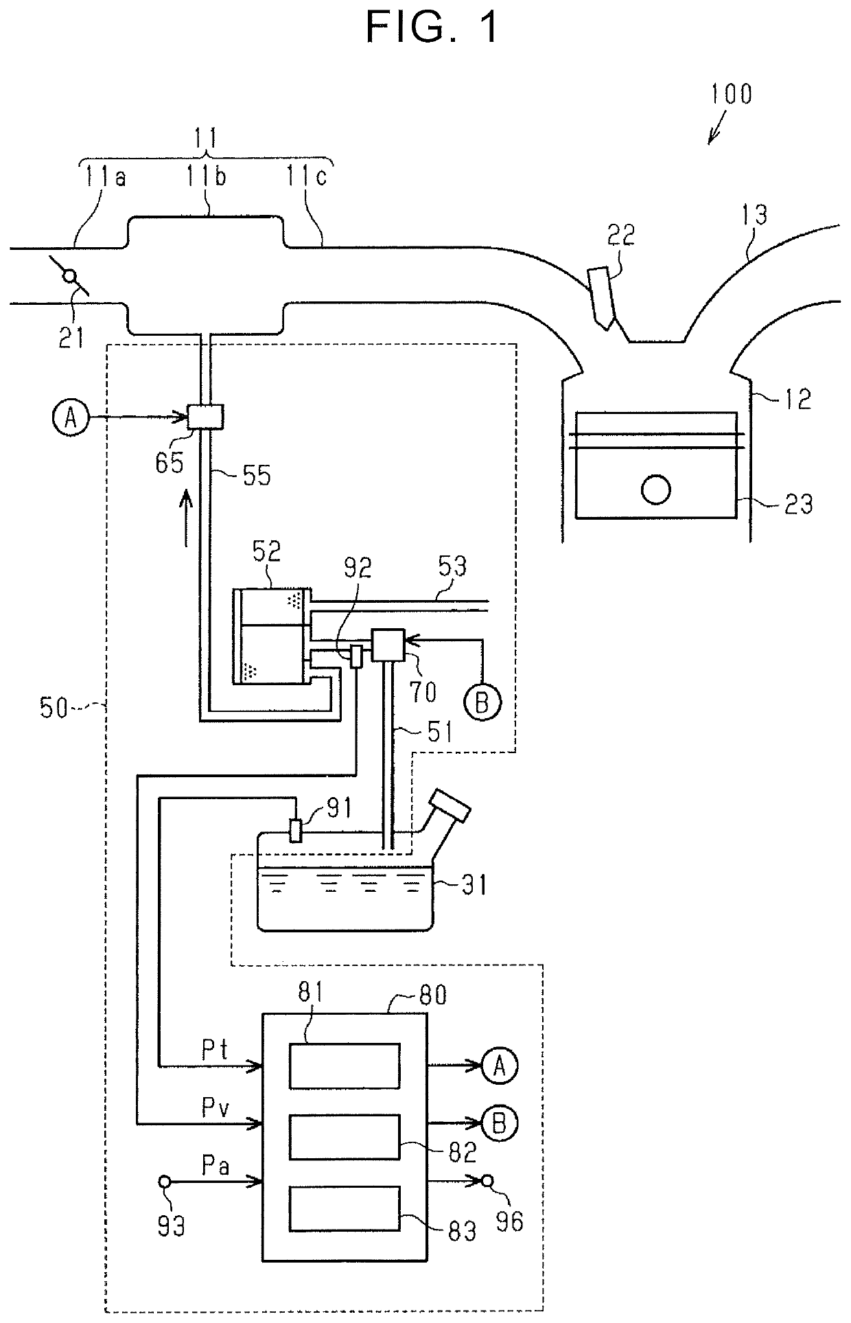
[0023]The embodiment of the disclosure will be described hereinafter with reference to FIGS. 1 to 5C. First of all, the schematic configuration of an internal combustion engine 100 to which the disclosure is applied will be described. Incidentally, in the following description, the simple mention of “upstream” and “downstream” means “upstream” and “downstream” in a direction in which intake air, exhaust gas, evaporative fuel, and outside air flow.

[0024]As shown in FIG. 1, the internal combustion engine 100 is equipped with an intake passage 11 for introducing intake air from outside the internal combustion engine 100. A throttle valve 21 is arranged in an upstream intake passage 11a as part of the intake passage 11. The throttle valve 21 controls the amount of intake air flowing through a flow channel of the upstream intake passage 11a by opening / closing the flow channel of the upstream intake passage 11a.

[0025]A downstream side of the upstream intake passage 11a is connected to a ...


PUM


Abstract

An evaporative fuel treatment apparatus includes a canister, a vapor passage, an outside air introduction passage, a purge passage that connects the canister and an intake passage to each other, a sealing valve configured to open / close a flow channel of the vapor passage, a tank internal pressure sensor, a pressure sensor configured to detect a vapor pressure; and an electronic control unit. The electronic control unit is configured to determine whether or not there is an abnormality in the tank internal pressure sensor based on a change in the vapor pressure in changing over the sealing valve from a closed state to an open state, when an amount of change in the tank pressure in changing over the sealing valve from the closed state to the open state is lower than a first predetermined value.

Description

INCORPORATION BY REFERENCE[0001]The disclosure of Japanese Patent Application No. 2018-103803 filed on May 30, 2018 including the specification, drawings and abstract is incorporated herein by reference in its entirety.BACKGROUND1. Technical Field[0002]The disclosure relates to an evaporative fuel treatment apparatus and a control method for an evaporative fuel treatment apparatus.2. Description of Related Art[0003]An evaporative fuel treatment apparatus of Japanese Patent Application Publication No. 2016-079851 (JP 2016-079851 A) is equipped with a canister that adsorbs evaporative fuel produced in a fuel tank. The canister is connected to the fuel tank via a vapor passage. An outside air introduction passage that introduces outside air into the canister is connected to the canister. The canister is connected to an intake passage via a purge passage. A sealing valve that opens / closes a flow channel of the vapor passage is attached to the vapor passage. Besides, a tank internal pres...

Claims


Application Information

Patent Timeline
Patent Type & Authority Patents(United States)
IPC IPC(8): F02D41/00F02M25/08B60K15/035
CPCF02D41/003B60K15/03504F02M25/0809F02D41/004F02D41/1401F02M25/0836F02M25/089F02D41/222F02D41/2464F02M35/0218F02M35/10222
Inventor AKITA, TATSUHIKO
Owner TOYOTA JIDOSHA KK
Why Eureka
Try Eureka