System and method for improved film cooling

a film cooling and film technology, applied in the field of film cooling, can solve the problems of high drilling speed, large heat affected zone, and deposition of coatings like tbcs, and achieve the effect of improving cooling effectiveness

Active Publication Date: 2010-11-11
GENERAL ELECTRIC CO
View PDF23 Cites 57 Cited by
  • Summary
  • Abstract
  • Description
  • Claims
  • Application Information

AI Technical Summary

Benefits of technology

[0011]FIG. 2 is a schematic illustration of an exemplary surface geometry formed employing the improved laser technique to accommodate the cooling holes in FIG. 1 to improve cooling effectiveness.

Problems solved by technology

However, the masking methods are not precise enough in terms of forming the geometries of predetermined dimensions and also result in deposition of the coatings like TBCs, into undesirable locations within the film holes.
Such laser processing results in a high drilling speed due to large pulse energy and high average power.
However, it also results in a large heat affected zone, undesirable degree of delamination, and over drilling.
On the other hand, shorter pulsed (2 mm in thickness, special applications in aviation etc.), these lasers have not been well developed into film cooling hole applications.

Method used


Image

  • System and method for improved film cooling
  • System and method for improved film cooling
  • System and method for improved film cooling

Examples


Embodiment Construction

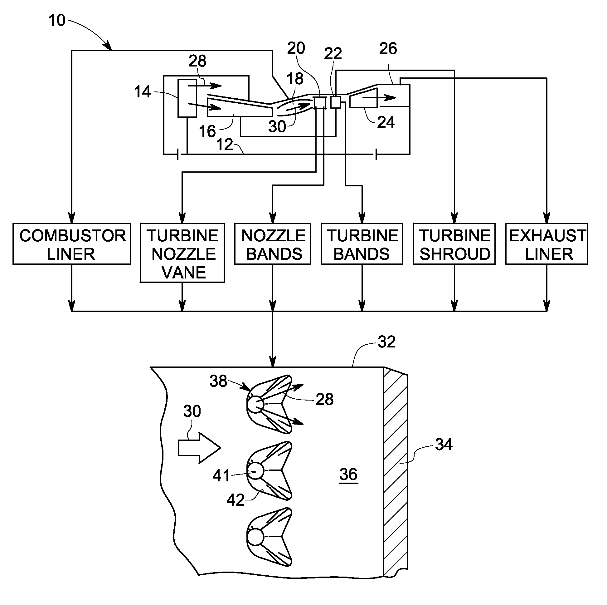
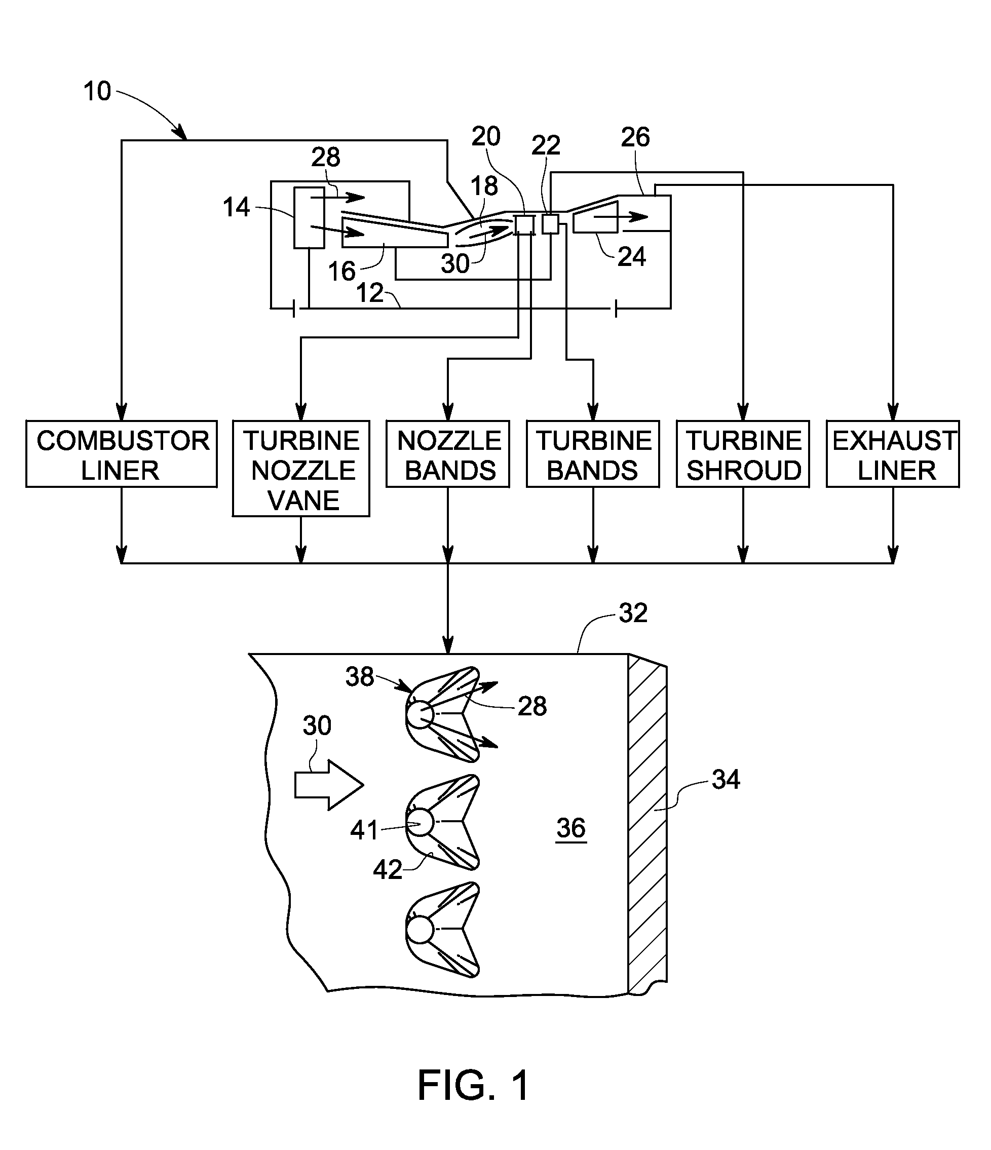
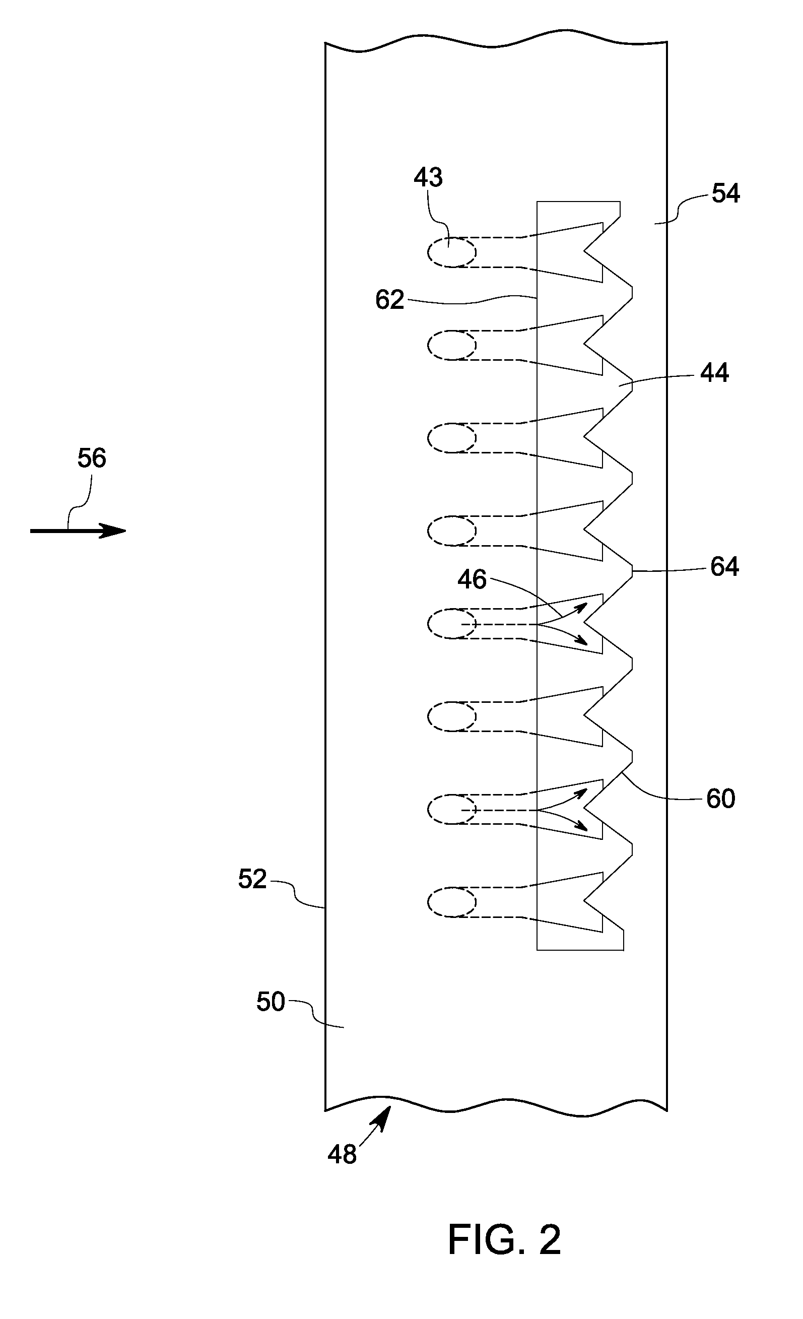
[0014]As discussed in detail below, embodiments of the invention include a system and method for producing one or more surface geometries and shapes to improve film cooling in a sample. The system and method disclose an improved laser machining technique via employing a pulsed laser with a shorter pulse duration, lower pulse energy, suitable wavelength, and higher cycle time. As used herein, the term ‘pulse duration’ refers to duration of each energy pulse output from the laser, and ‘cycle time’ refers to repetition rate or frequency of the pulses output from the laser. An exemplary application of the lasers, as discussed in detail below, is in film cooling holes formed on a substrate such as, but not limited to, an airfoil in a turbine engine. It should be noted that the technique may be employed in various other applications such as, but not limited to, film cooling of combustor components, turbine endwalls and platforms, turbine shrouds, repaired components and also the selective...


PUM

PropertyMeasurementUnit
energyaaaaaaaaaa
wavelengthaaaaaaaaaa
diameteraaaaaaaaaa

Abstract

A system for producing at least one trench to improve film cooling in a sample is provided. The system includes at least one laser source outputting at least one pulsed laser beam. The pulsed laser beam includes a pulse duration including a range less than about 50 μs, an energy per pulse having a range less than about 0.1 Joule, and a repetition rate with a range greater than about 1000 Hz. The system also includes a control subsystem coupled to the laser source, the control subsystem configured to synchronize a position of the sample with the pulse duration and energy level in order to selectively remove at least one of a thermal barrier coating, a bondcoat and a substrate metal in the sample to form the at least one trench.

Description

BACKGROUND[0001]The invention relates generally to film cooling at high temperatures, and more specifically, to formation of trenches to improve film cooling.[0002]A variety of components in aircraft engines and stationary power systems are operated in extremely hot environments. These components are exposed to hot gases having temperatures up to about 3800 degrees Fahrenheit, for aircraft applications, and up to about 2700 degrees Fahrenheit for stationary power generation applications. To cool the components exposed to the hot gases, these “hot gas path” components typically have both internal convection and external film cooling. For example, a number of cooling holes may extend from a relatively cool surface of the component to a “hot” surface of the component. Film cooling is of a higher benefit since it decreases incident heat flux from hot gases to surfaces of components.[0003]The coolant typically is compressed air bled off a compressor, which is then bypassed around the eng...

Claims


Application Information

Patent Timeline
Patent Type & Authority Applications(United States)
IPC IPC(8): B23K26/38
CPCB23K26/0635B23K26/388F01D25/12F01D25/285F05D2230/13Y02T50/672Y02T50/676F05D2260/202F05D2260/221Y02T50/67B23K26/0624B23K26/389Y02T50/60
Inventor BUNKER, RONALD SCOTTZHANG, WENWUSCHEIDT, WILBUR DOUGLASAZER, MAGDI NAIMJONES, MARSHALL GORDONLEE, CHING-PANG
Owner GENERAL ELECTRIC CO
Why Eureka
Try Eureka