
Diffraction element, manufacturing method for diffraction element, and spectrometer using the same

a technology of diffraction element and manufacturing method, which is applied in the direction of spectrometer/spectrophotometry/monochromator, optical radiation measurement, instruments, etc., can solve the problems of undesired diffracted light increase, deterioration of spectroscopy precision, etc., to prevent the intensity decrease of light beam entering the light receiving unit without a decrease in diffraction efficiency, and high-quality diffraction

Active Publication Date: 2010-11-11
CANON KK
View PDF7 Cites 25 Cited by
  • Summary
  • Abstract
  • Description
  • Claims
  • Application Information

AI Technical Summary

Benefits of technology

[0052]It is an object of the present invention to provide a highly accurate diffraction element that may prevent an intensity decrease of a light beam entering a light receiving unit without a decrease in diffraction efficiency and without a problem of flare or the like, a manufacturing method for the diffraction element, and a spectrometer using the same.
[0064]According to the present invention, the highly accurate diffraction element that may prevent the intensity decrease of the light beam entering the light receiving unit without the decrease in diffraction efficiency and without the problem of flare or the like, the manufacturing method for the diffraction element, and the spectrometer using the same may be provided.

Problems solved by technology

However, when the diffraction grating 201 is processed on the “z-toric surface” as illustrated in FIG. 21, the following problem occurs.
A spectroscopic analysis by use of the diffraction gratings illustrated in FIG. 26 causes a problem in which the precision in spectroscopy is deteriorated due to the difference in pitch of the diffraction gratings depending on the distance from the xy plane with z=0 as can be understood from FIG. 26.
Further, undesired diffracted light increases, and hence a problem of flare or the like occurs.

Method used


Image

  • Diffraction element, manufacturing method for diffraction element, and spectrometer using the same
  • Diffraction element, manufacturing method for diffraction element, and spectrometer using the same
  • Diffraction element, manufacturing method for diffraction element, and spectrometer using the same

Examples


embodiment

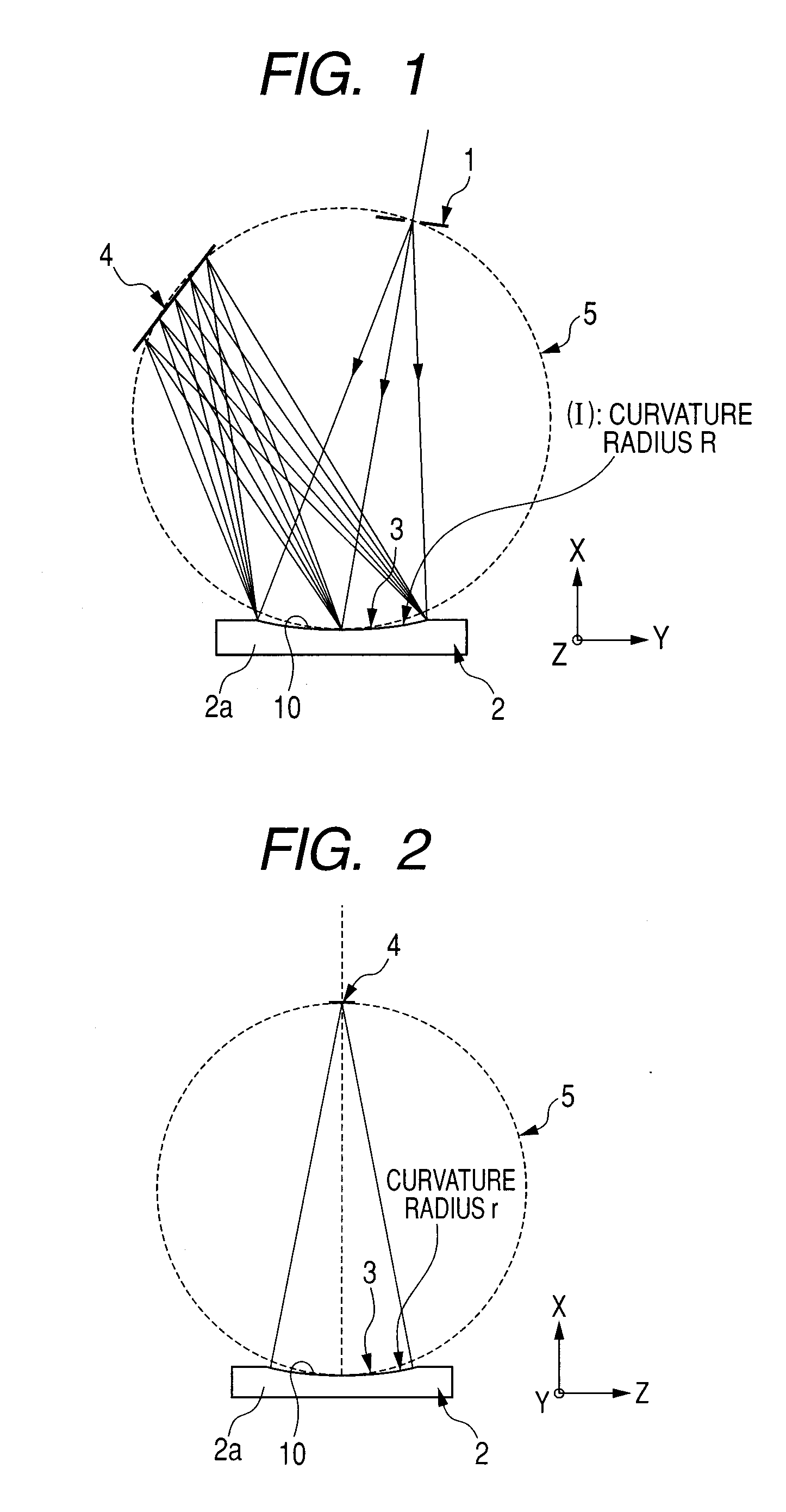
[0098]FIG. 1 is a principal part cross sectional view of a spectrometer in a spectral direction which uses a diffraction element according to an embodiment of the present invention.

[0099]In FIG. 1, an incident slit 1 as an incident light introducing unit allows a light beam (light) from a subject (toner image) for spectral measurement, for example, to enter a diffraction element 2 that is described later. In this embodiment, the incident slit 1 is disposed on a part of a Rowland circle of the diffraction element 2 as described later.

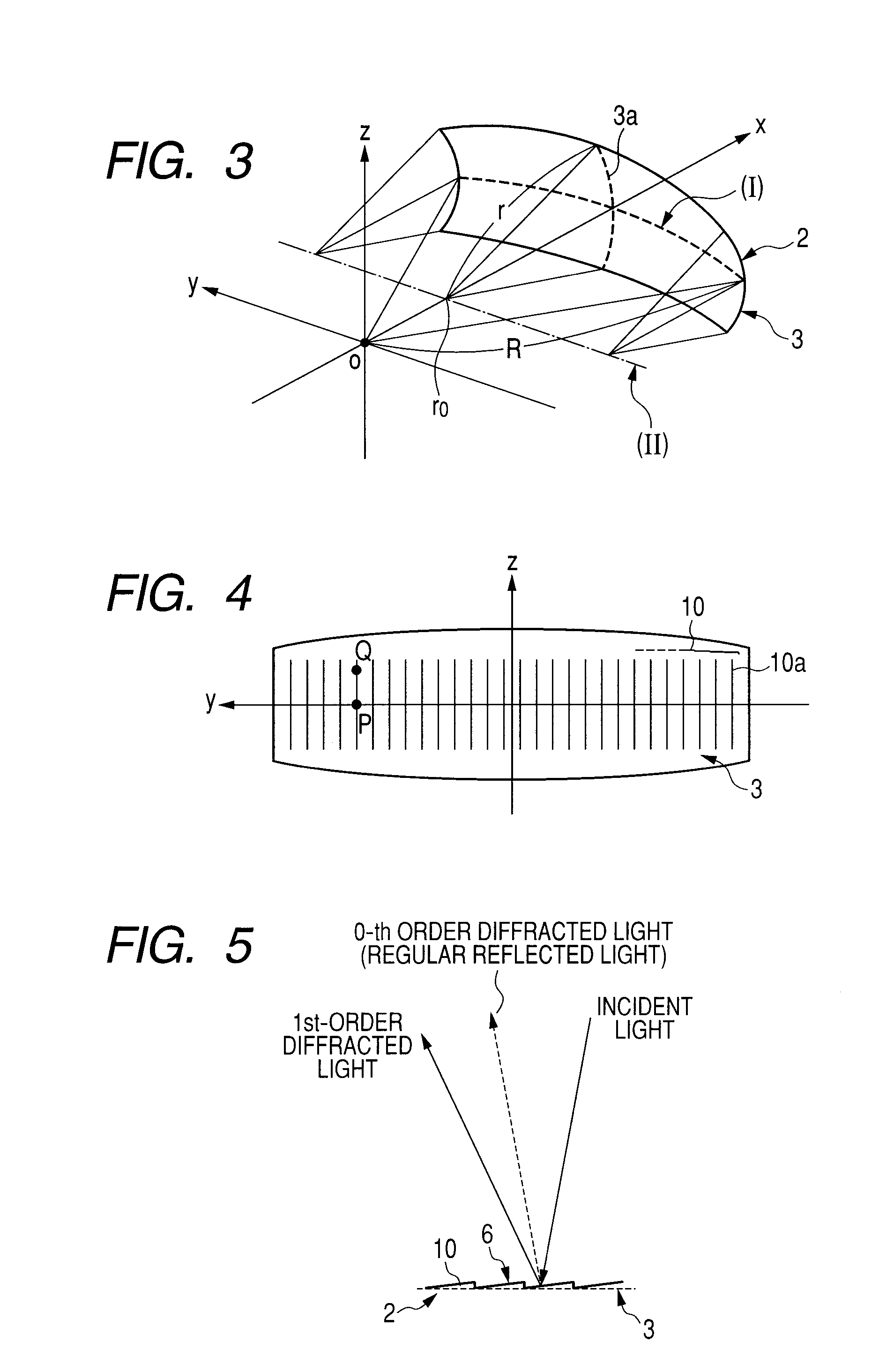
[0100]The diffraction element 2 has a diffraction grating 10 (constituted of multiple gratings) formed on a curved surface (surface) 3 of a substrate 2a, in which fine grooves are formed in the direction perpendicular to the paper face. In addition, the curved surface 3 on which the diffraction grating 10 is formed is a concave surface.

[0101]The diffraction element 2 in this embodiment includes a reflective diffraction element. Hereinafter, the diffracti...


PUM

PropertyMeasurementUnit
wavelength rangeaaaaaaaaaa
incident angleaaaaaaaaaa

Abstract

Objects are to obtain a highly accurate diffraction element that may prevent an intensity decrease of a light beam entering a light receiving unit without a decrease in diffraction efficiency and without a problem of flare or the like, a manufacturing method for the diffraction element, and a spectrometer using the same. A diffraction element (2) includes a diffraction grating formed on a substrate having a curved surface. In the diffraction element (2), the curved surface (3) has an anamorphic shape formed by pivoting a curved line (I) in a plane about a straight line (II) in the same plane serving as a rotation axis, and gratings (10a) of the diffraction grating (10) exist in cross sections orthogonal to the rotation axis.

Description

BACKGROUND OF THE INVENTION[0001]1. Field of the Invention[0002]The present invention relates to a diffraction element used in a spectrometer which is used for spectral analysis for a light beam (light), a manufacturing method (processing method) for a diffraction element, and a spectrometer using the same.[0003]Further, the present invention relates to a color image forming apparatus which uses the spectrometer using the diffraction element so as to perform spectral analysis for an output image.[0004]2. Description of the Related Art[0005]Most conventional spectrometers use a diffraction element. In particular, there is provided a well-known compact spectrometer having a structure in which a slit is disposed at an arbitrary position on the Rowland circle of a concave diffraction element (see Japanese Patent Application Laid-Open No. H05-340813 and Japanese Patent Application Laid-Open No. 2007-333581).[0006]Note that the concave diffraction element means a diffraction element forme...

Claims


Application Information

Patent Timeline
Patent Type & Authority Applications(United States)
IPC IPC(8): G02B5/18B23B3/00G01J3/28
CPCB23C3/00B23C2226/31G01J3/18G01J3/20G01J3/50G02B5/1842G02B5/1861G02B27/0944Y10T82/10
Inventor ISHIBE, YOSHIHIRO
Owner CANON KK
Learn More