Ir thermometer thermal isolation tip assembly

Active Publication Date: 2010-11-11
WELCH ALLYN INC
View PDF52 Cites 16 Cited by
  • Summary
  • Abstract
  • Description
  • Claims
  • Application Information

AI Technical Summary

Benefits of technology

[0029]In another aspect, a method to enhance the thermal isolation of an IR thermometer IR sensor during a temperature measurement includes the steps of: providing an IR thermometer having at least one air gap disposed between an

Problems solved by technology

One of the problems encountered in IR thermometry is that the electrical output of most IR sensors is a function of both the IR radiation received through the optical sensor window of the IR sensor, as well as the temperature of the sensor case or housing, typically a metal can.
However, even with temperature sensing of the IR sensor can, there can be measurement errors related to changing temperature gradients across the instrument, particularly across elements of the IR thermometer in and near the optical path to the IR sensor and in the vicinity

Method used


Image

  • Ir thermometer thermal isolation tip assembly
  • Ir thermometer thermal isolation tip assembly
  • Ir thermometer thermal isolation tip assembly

Examples


Embodiment Construction

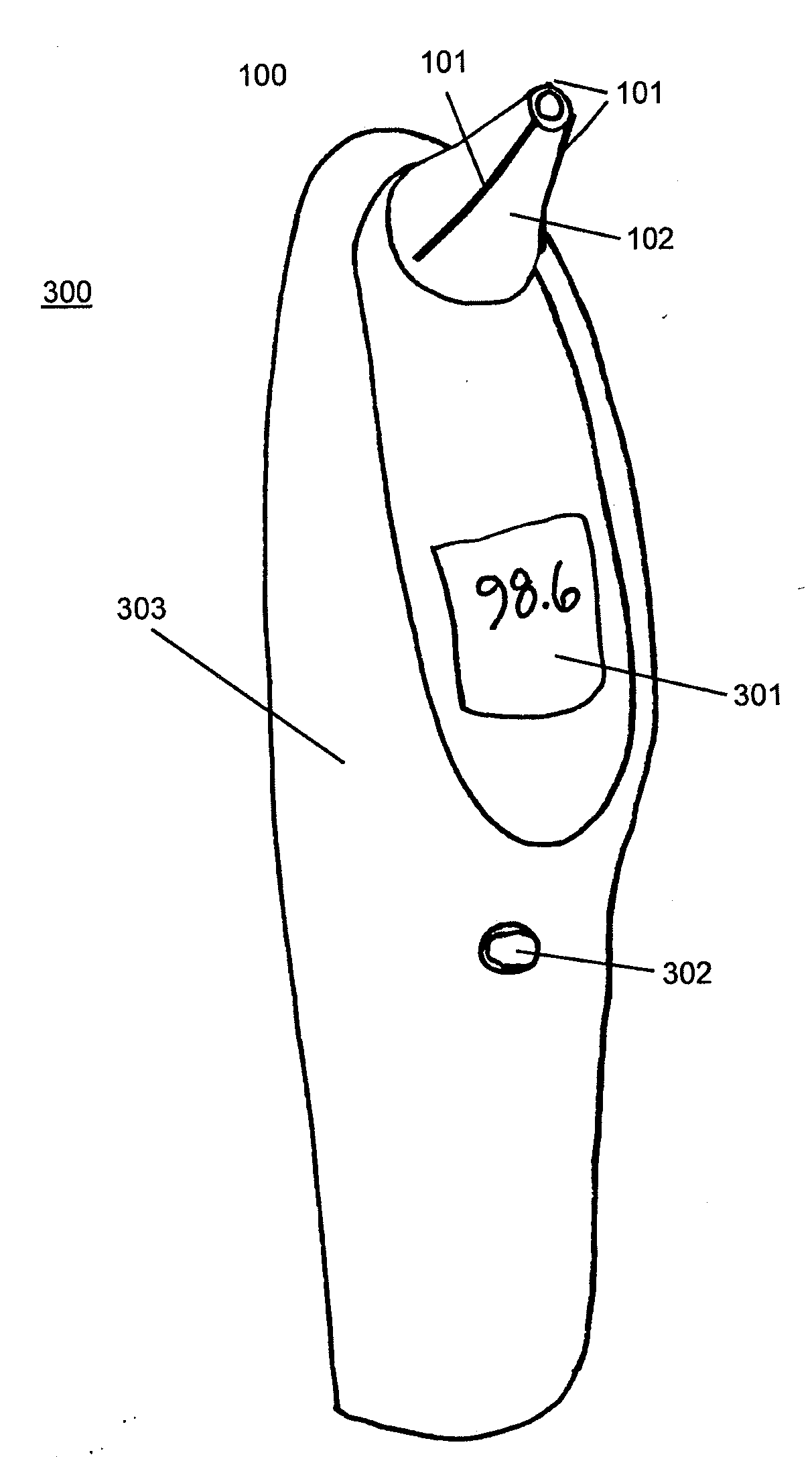
[0060]For purposes of background, there are at least three (3) thermal paths of undesirable heat flow from the outside environment into an IR tip assembly of an IR thermometer. As discussed above, one path is directly from an outer surface of a disposable cover, into the tip section of the IR tip assembly. Another path is from the tip section of the IR tip assembly into an internal heat sink. Also, there can be an undesirable heat flow from the tip section directly to the IR sensor. An IR tip assembly, or thermally isolating IR tip assembly as described below, includes features to reduce undesired heat flow, including a new approach to thermally isolate a disposable cover from the tip assembly.

[0061]In the prior art, there has been an effort to reduce undesired heat flow that flows through a cover attached to an IR tip assembly. One approach has been to make disposable covers from one or more thermally insulating materials. A nearly opposite approach, described herein and using a re...


PUM


Abstract

An IR tip assembly includes a shroud having at least one feature that permits releasable attachment of a disposable cover fitted to a shroud. When the disposable cover is fitted to the shroud, at least one air gap is defined between the shroud and the disposable cover. An IR sensor disposed within the IR tip assembly is mechanically and thermally coupled to a heat sink. The at least one defined air gap creates a thermal isolation between the disposable cover and the disposed IR sensor. There can also be airflow through the at least one air gap. Apparatus and methods to create the airflow are described.

Description

FIELD OF THE INVENTION[0001]This invention relates generally to a tip assembly for an IR thermometer and more specifically to an IR tip assembly having improved thermal isolation.BACKGROUND OF THE INVENTION[0002]Infrared (IR) thermometers, such as IR ear thermometers, are in wide use today. IR thermometers employ an IR sensor to receive and measure IR radiation emanating from a surface. In the case of the IR ear thermometer, the IR sensor detects IR radiation that emanates from the surface of the tympanic membrane. One of the problems encountered in IR thermometry is that the electrical output of most IR sensors is a function of both the IR radiation received through the optical sensor window of the IR sensor, as well as the temperature of the sensor case or housing, typically a metal can.[0003]Some IR thermometer instruments measure the temperature of the IR sensor housing in order to make a correction to the sensor electrical output signal. However, even with temperature sensing o...

Claims


Application Information

Patent Timeline
IPC IPC(8): G01J5/00
CPCA61B5/01G01J5/021G01J5/02A61B5/6817
Inventor LANE, JOHN A.QUINN, DAVID E.MARTIN, SCOTT A.STONE, RAY D.MULLIN, MATTHEW D.MEYERSON, CRAIG M.
Owner WELCH ALLYN INC
Why Eureka
Try Eureka