Rotating part position and change finding method and apparatus

a technology of rotating parts and position finding, applied in the direction of programme control, measurement/indication equipment, instruments, etc., can solve the problems of unreliable position data, unreliable repeat recording of laser beam obstruction, and inability of the technique to control rotating tools at high speed, etc., to achieve high speed and high position accuracy

Active Publication Date: 2010-11-11
CONOPTICA
View PDF17 Cites 25 Cited by
  • Summary
  • Abstract
  • Description
  • Claims
  • Application Information

AI Technical Summary

Benefits of technology

[0021]The present invention relies on optical contactless sensing technology and aims at providing an in-the-process quality control technique that regularly and automatically can provide updates of position information for key rotating machine parts without having to rely on external quality control and calibration means.
[0022]The present invention determines the position and size of parts rotating at high speeds, even when the parts are ...

Problems solved by technology

Except for the laser beam obstruction the mentioned techniques do not have the capability, and sufficient temporal resolution, to control rotating tools at high speed.
To find the geometry of a rotating machine part, specifically a work tool tip, rep...

Method used


Image

  • Rotating part position and change finding method and apparatus
  • Rotating part position and change finding method and apparatus
  • Rotating part position and change finding method and apparatus

Examples


example 1

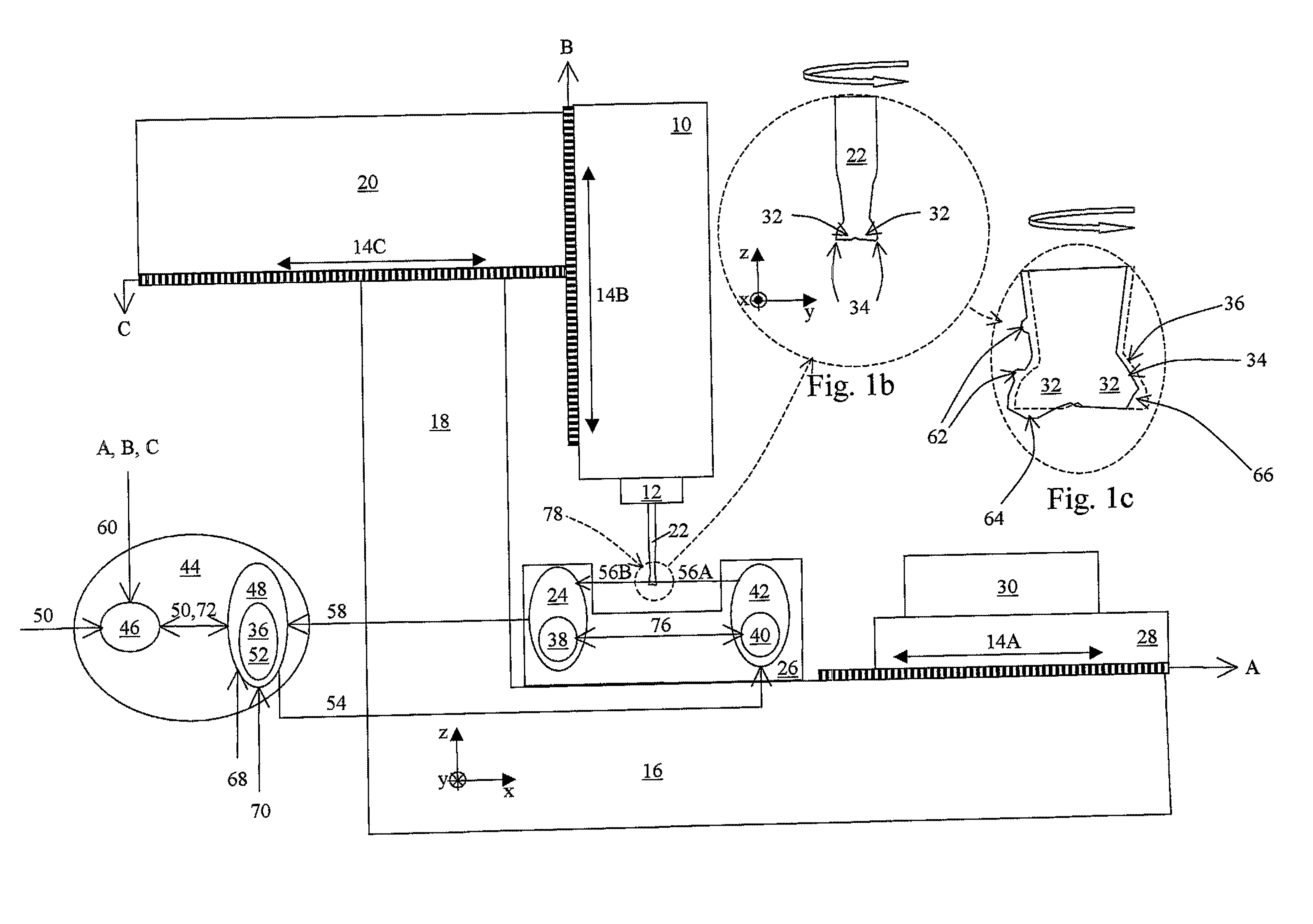
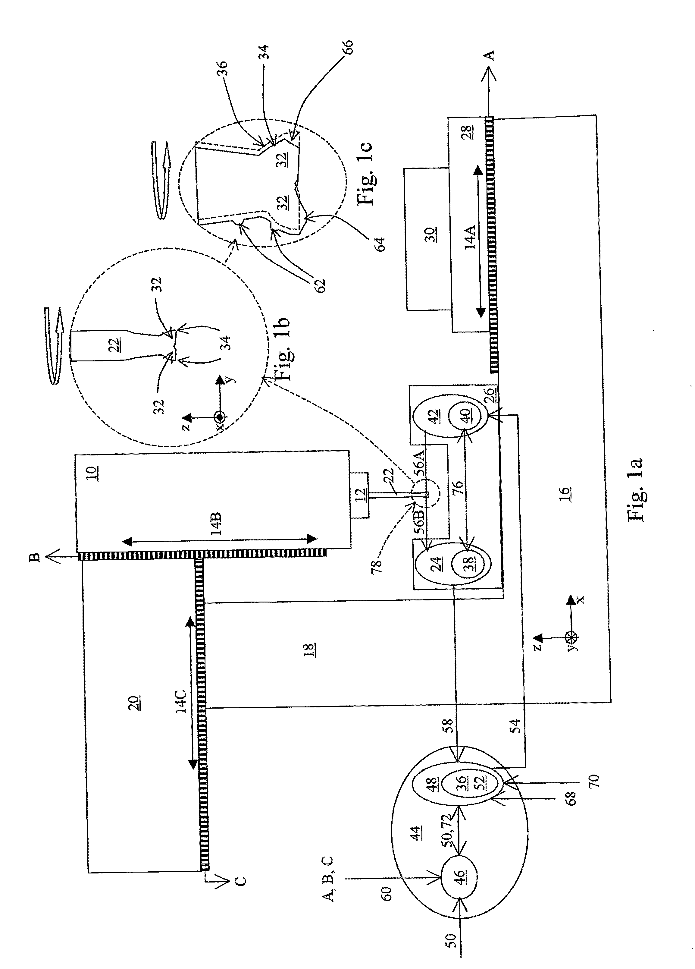
[0043]FIG. 1a is a schematic drawing illustrating, by way of example, a machine that may represent any machine such as a milling machine, drilling machine, turning machine, Die sinking EDM, Wire EDM, CMM, or similar. These machines can be equipped with a range of different mechanical configurations, but all can be equipped with an apparatus according to the present invention. We indicate some key elements of these machines as a work piece carrier 28 (performing movements like two orthogonal translations x, y and rotations around the same axes), a work tool carrier 10 (in this example performing two translations, in the x and z directions), a work tool chuck 12, position encoders 14A, 14B, 14C, and a support structure 16. The support structure is in this example indicated to include a base support 16, a machine support link 18, and a work tool support 20. The purpose of this machine configuration and example is to find the cutter edge positions of a work tool 22 relative to the posit...

example 2

[0061]This example is similar to Example 1, but the milling tool 22 is diameter is larger and rotating at a slower speed of e.q. 7200 rpm (rotations per minute). The illuminator pulses are synchronized 76 with the optical detector image timing. The edges 34 in the present example might be contaminated by residues of oil, water, machining chips, etc. The milling tool 22 is a tool with ID (Identification Number). A fiducial pattern image model 52, specifically made for this identified tool, is applied. Example 1 shows how such a model can be made.

[0062]The present example is illustrated in FIGS. 1a-c. The part position finder 44 can be embodied as process within a computer, personal computer, dedicated processor, or similar. In this example, we shall assume that part position finder 44 processes are carried out by means of a computer that takes care of both the machine NC (Numerical Control) together with processes dedicated to the control and monitor of the optical assembly 26. The r...

example 3

[0076]This example is similar to Examples 1 and 2, but the timing of the optical detector 24 is synchronized 76 by the illuminator 42, and the milling tool 22 is a used tool with seven cutters 32. I.e. in addition to the fact that the cutter edges might be contaminated by residues of oil, water, machining chips, etc., the cutter edge geometry might be distorted due to buildup 64 and wear 66. The present example also demonstrates how a fiducial pattern image model 52, adapted from the geometry of the same tool in a previous stage, helps characterizing this used tool.

[0077]The present example is illustrated in FIGS. 1a-c. The part position finder 44 can be embodied as process within a computer, personal computer, dedicated processor, or similar. In this example we shall assume that part position finder 44 processes are carried out by means of two computers that exchange messages, where one computer takes care of the machine NC (Numerical Control) 46 while the other 48 controls process...


PUM


Abstract

An apparatus and a method for finding to find positional relationships and geometrical changes of at least one rotating part attached to or forming part of a machine when said part is in a rotating mode, said changes of the part caused by its state of production and use, to determine any locations on said rotating part which exhibit contaminants, and to subsequently remove or compensate effects of such contaminants present on the rotating part.

Description

BACKGROUND OF THE INVENTIONDescription of the Related Art[0001]The present invention relates to the field of technical arrangements and methods for determining positions and changes, and more specifically to an apparatus as defined in the preamble of claim 1 and a method as defined in the preamble of claim 41 for determining positional deviation and changes that has occurred in the course of a mechanical machining operation or a mechanical control activity.[0002]Further, the invention relates to a quality control touch probing method for enabling a position of a quality control tool in the form of a touch probe to be related to position of a rotating part, as defined in the preamble of claims 66.[0003]In order to simplify this disclosure by uniquely identifying important parts related to a typical machine system, which may be a system for mechanical quality control, the following explains the use of some general terms.[0004]The term “machine” denotes any production or quality contro...

Claims


Application Information

Patent Timeline
IPC IPC(8): G05B13/04
CPCB23Q17/09G01B21/045B23Q17/24B23Q17/2457
Inventor SLETTEMOEN, GUDMUNNASKELAND, CHRISTIANSTENBERG, ESPENGREGER, TORSTEIN OSABESUCHET, JEAN-PHILIPPE
Owner CONOPTICA
Why Eureka
Try Eureka