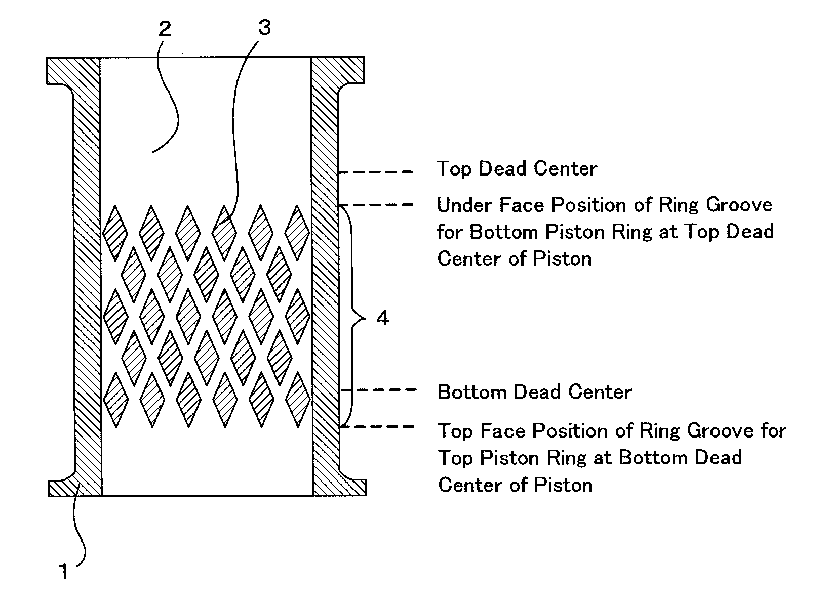
Cylinder
a technology of cylinders and piston rings, which is applied in the direction of reciprocating piston engines, positive displacement engines, cylinders, etc., can solve the problems of deteriorating scuffing resistance, reducing and reducing the friction between the piston ring and the bore surface of the cylinder, so as to improve the energy efficiency of the apparatus using the cylinder. , the effect of reducing the friction between the piston ring and the bore surfa
- Summary
- Abstract
- Description
- Claims
- Application Information
AI Technical Summary
Benefits of technology
Problems solved by technology
Method used
Image
Examples
first embodiment
A. First Embodiment
Cylinder Liner Type
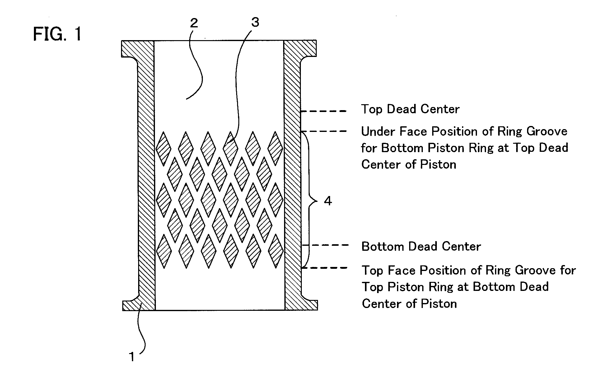
[0040]In a cylinder of the first embodiment of the present invention, a cylinder liner is fixed to the inside of the cylinder, and the plurality of recesses is formed in the bore surface of the cylinder liner. In the embodiment, the bore surface of the cylinder and the outer wall surface of the cylinder liner are fixed, and the piston slides on the bore surface of the cylinder liner. Consequently, the recesses may not be provided for the bore surface of the cylinder to which the outer wall surface of the cylinder liner is fixed. Instead, the recesses are formed in the bore surface of the cylinder liner on which the cylinder actually slides.
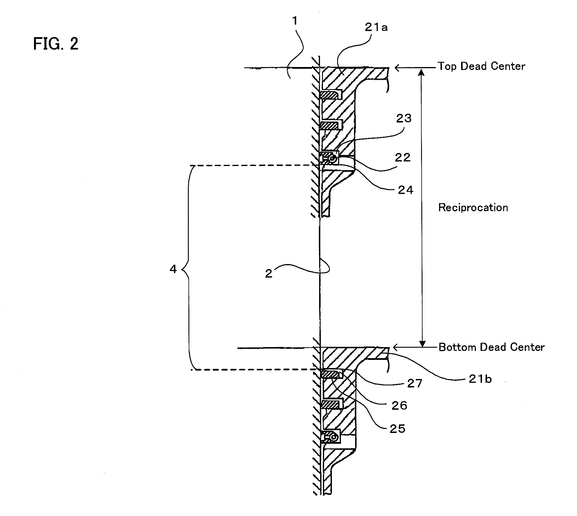
[0041]In the following, the cylinder of the embodiment will be described with reference to the drawings. FIG. 1 is an explanatory diagram showing an example of a formation position of recesses in the cylinder liner bore surface of the cylinder liner fixed to the inside of the cylinder of the embodiment. As sho...
second embodiment
B. Second Embodiment
Liner-Less Type
[0074]In a cylinder of a second embodiment of the invention, a cylinder liner as in “First Embodiment” is not fixed, but the recesses are formed directly in the bore surface of the cylinder, and a piston slides directly on the bore surface of the cylinder.
[0075]Any cylinder may be used in the embodiment as long as recesses as described above are formed in the bore surface of the cylinder. Factors such as the dimensions and material of the cylinder can be properly adjusted according to the dimensions, operating temperature, and the like of an engine, a compressor, or the like to which the cylinder is used. There is a case that surface process is performed on the bore of the cylinder. The embodiment can be applied regardless of factors such as the presence / absence of such a surface process and the quality of the cylinder base material.
[0076]In the embodiment, from the viewpoint of reducing reciprocation friction between the piston ring and the bore s...
example 1
[0080]A cylinder liner was processed by the following method, and reciprocation frictional force of the cylinder liner was measured.
[0081](Processing on Cylinder Liner)
[0082]Recesses were formed in the stroke center region of a cylinder liner (material: FC250) having a dimension (mm) shown in FIG. 8 with a masking sheet shown in FIG. 9 by the following procedure. The recesses were formed in the shape and layout shown in FIG. 5A.
(1) The masking sheet was adhered to the bore surface of the cylinder liner.
(2) As shown in FIG. 10, a cylinder 91 made by a copper sheet (sheet thickness: 0.5 mm and the outside diameter of the cylinder: 74 mm) was inserted in a cylinder liner 92 and fixed so that the clearance between the cylinder 91 made by a copper sheet and the cylinder liner 92 becomes uniform.
(3) The cylinder liner 92 of (2) was inserted in a container 93.
(4) A corrosion solution 94 was poured into the container 93.
(5) A voltage of 1.5 V was applied using the cylinder liner 92 as an an...
PUM
 Abstract
Description
Claims
Application Information
 - R&D
- Intellectual Property
- Life Sciences
- Materials
- Tech Scout
- Unparalleled Data Quality
- Higher Quality Content
- 60% Fewer Hallucinations
Browse by: Latest US Patents, China's latest patents, Technical Efficacy Thesaurus, Application Domain, Technology Topic, Popular Technical Reports.
© 2025 PatSnap. All rights reserved.Legal|Privacy policy|Modern Slavery Act Transparency Statement|Sitemap|About US| Contact US: help@patsnap.com


