Energy efficient and fast charge modes of a rechargeable battery

a rechargeable battery, energy-efficient technology, applied in the field of portable power, can solve the problems of not providing current devices such as notebook pcs also do not provide a mechanism for the user to activate an accelerated charging mode of the battery, and the current required for such fast charging modes and normal system load often exceed the power. , to achieve the effect of higher energy-efficiency operation

Inactive Publication Date: 2010-11-18
BOSTON POWER INC
View PDF102 Cites 184 Cited by
  • Summary
  • Abstract
  • Description
  • Claims
  • Application Information

AI Technical Summary

Benefits of technology

[0010]In still further embodiments of the invention, the first and second power states can be enabled in response to a user selection of an energy-efficient power mode to power the electronic device. This selection may be made among a plurality of different power and charge modes, including a “normal” power mode and a “fast” charge mode. Such modes can include a power state in which a circuit is switched to provide a low current at the AC-to-DC adapter to charge the battery at a low rate and provide primary power to the electronic device. The low rate of charge may be less than 1 C, such as a typical charge rage of 0.7 C. The higher current provided at the second power state may result in a higher energy efficiency operation of the AC-to-DC adapter.

Problems solved by technology

Current notebook PCs and other battery powered devices do not provide a mechanism for the user to activate an environment-conserving power efficient charging and discharging mode of the battery pack, AC adapter and device.
Current devices such as notebook PCs also do not provide a mechanism for the user to activate an accelerated charging mode of the battery.
Furthermore, the current required for such fast charging modes plus normal system loads will often exceed the power capacity of a typical AC adapter and will require the notebook to reduce power consumption itself in order to provide sufficient power for accelerated charging of the battery.

Method used


Image

  • Energy efficient and fast charge modes of a rechargeable battery
  • Energy efficient and fast charge modes of a rechargeable battery
  • Energy efficient and fast charge modes of a rechargeable battery

Examples


Embodiment Construction

[0031]A description of example embodiments of the invention follows.

[0032]The teachings of all patents, published applications and references cited herein are incorporated by reference in their entirety.

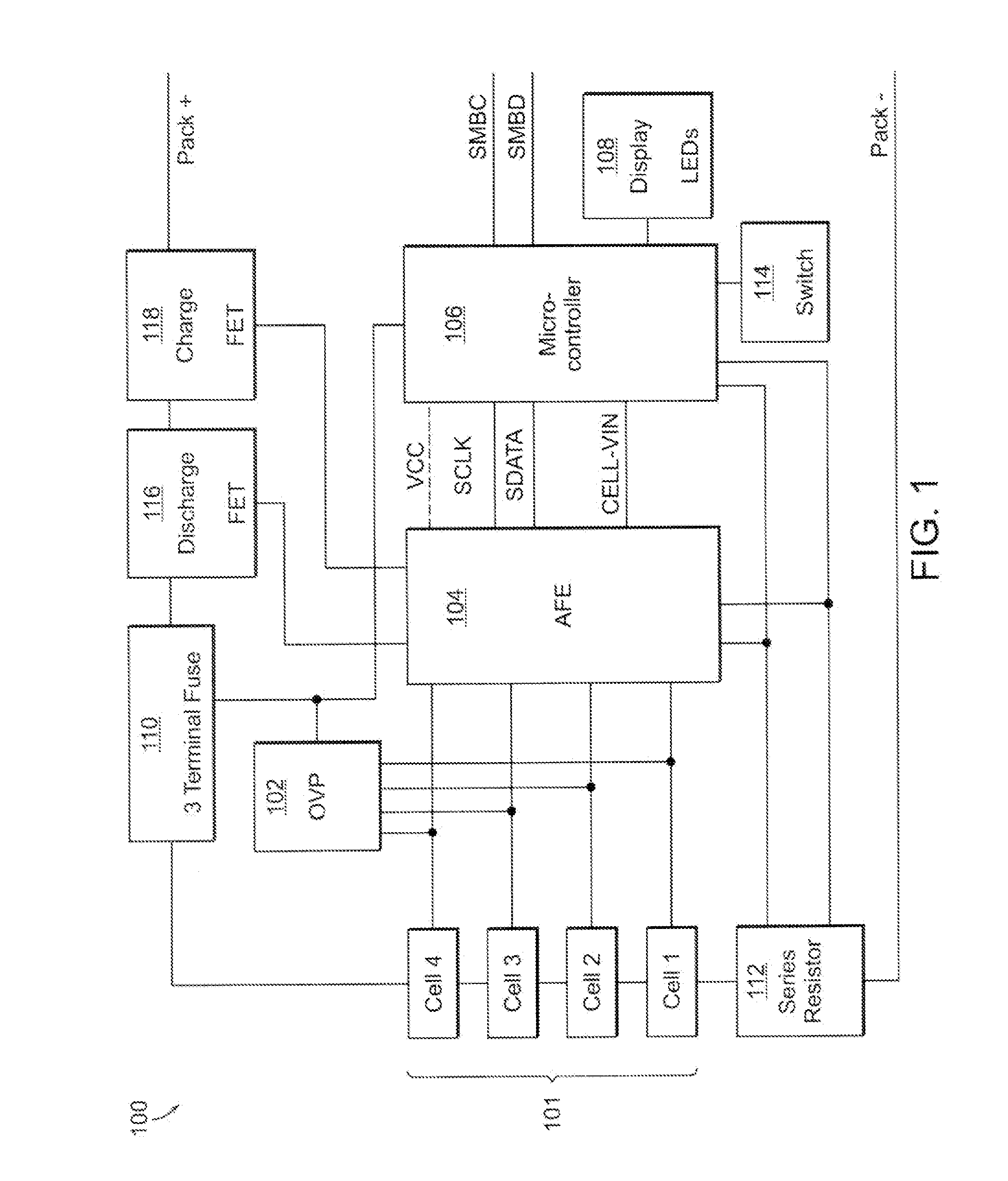
[0033]FIG. 1 illustrates a functional block diagram of the electronic circuitry 100 in a battery pack as used in current practice upon which the present embodiment may be implemented. In FIG. 1, a multiple cell battery 101 may be connected to an independent overvoltage protection integrated circuit (OVP) 102, an Analog Front End protection integrated circuit (AFE) 104, and a battery monitor integrated circuit microcontroller (microcontroller) 106. One with skill in the art will understand that the present invention is not limited to the aforementioned electronic circuitry of the schematic illustrated in FIG. 1.

[0034]The OVP 102 may allow for monitoring of each cell of the battery pack by comparing each value to an internal reference voltage. By doing so, the OVP 102 may be able to in...


PUM


Abstract

A method of providing power to an electronic device in an energy-efficient manner includes transitioning between power states corresponding to charging and discharging a battery. The state of charge of the battery is detected. Upon detecting a high threshold state of charge, an external power source such as an AC-to-DC adapter is disabled, and the battery to provides primary power to the electronic device. Upon a low threshold state of charge, the AC-to-DC adapter is controlled to provide a high current output to charge the battery and provide primary power to the electronic device. The power states, when cycled over time based on the state of the battery, provide for an energy-efficient method of powering the electronic device.

Description

RELATED APPLICATIONS[0001]This application claims the benefit of U.S. Provisional Application No. 61 / 179,182, filed on May 18, 2009, the entire teachings of which are incorporated herein by reference.BACKGROUND OF THE INVENTION[0002]The portable power industry has traditionally been using charge rates between 0.7 C and 1 C when charging electronic devices, which is the rate used for laptop computers. This current allows the notebook computer's battery pack to be charged at currents that are 70% to 100% of the value of rated capacity of the cells. For example, in a battery pack containing 18650 cells, rated at 2.2 Ah, in a 2p3s configuration (two cells in parallel, three cells in series), a charging current of 1 C would be equivalent to a charging current of 4.4 A for the pack. This charging current is allowed until a maximum voltage (Vmax) is reached, which is typically set at about 4.2V. Once Vmax has been reached, the current is lowered by control circuitry to disallow, in this ex...

Claims


Application Information

Patent Timeline
Patent Type & Authority Applications(United States)
IPC IPC(8): H02J7/04H02J7/00
CPCY02B40/90H02J7/0093H02J7/00711Y02B40/00
Inventor ONNERUD, PERPARTIN, PHILLIP E.JANSEN, ECKART W.MILNE, SCOTT
Owner BOSTON POWER INC
Why Eureka
Try Eureka