Cascaded Raman Fiber Laser System Based on Filter Fiber

a cascaded raman fiber and laser system technology, applied in the field of optical fiber devices and methods, can solve the problems of system instability, prior art system b>20/b> suffers from a number of known drawbacks and limitations, and achieves the effect of reducing the operating threshold and improving device efficiency and operation

Inactive Publication Date: 2010-11-18
OFS FITEL LLC
View PDF9 Cites 22 Cited by
  • Summary
  • Abstract
  • Description
  • Claims
  • Application Information

AI Technical Summary

Benefits of technology

[0017]To reduce the operating threshold and improve device efficiency and operation, the first cavity, which is configured to provide ionic gain, is nested inside the subsequent cavities which provide Raman gain at the first and higher Stokes shifts. With such a structure, light at the first gain wavelength is not be subjected to the loss from the elements used to form the other cavities.

Problems solved by technology

The prior art system 20 suffers from a number of known drawbacks and limitations.
While high power has been demonstrated from such a system, the coupled cavity nature of the setup in FIG. 1 has serious implications on long-term reliable operation.
In particular, the coupled cavity can cause the system to become unstable and generate pulses with sufficiently high peak power to damage components.
In addition, it is possible for light from intermediate Stokes orders generated in the Raman laser to propagate back into the Yb amplifier and back to the pump diodes, causing them to fail.
It will be apparent that this is also detrimental.

Method used


Image

  • Cascaded Raman Fiber Laser System Based on Filter Fiber
  • Cascaded Raman Fiber Laser System Based on Filter Fiber
  • Cascaded Raman Fiber Laser System Based on Filter Fiber

Examples


Embodiment Construction

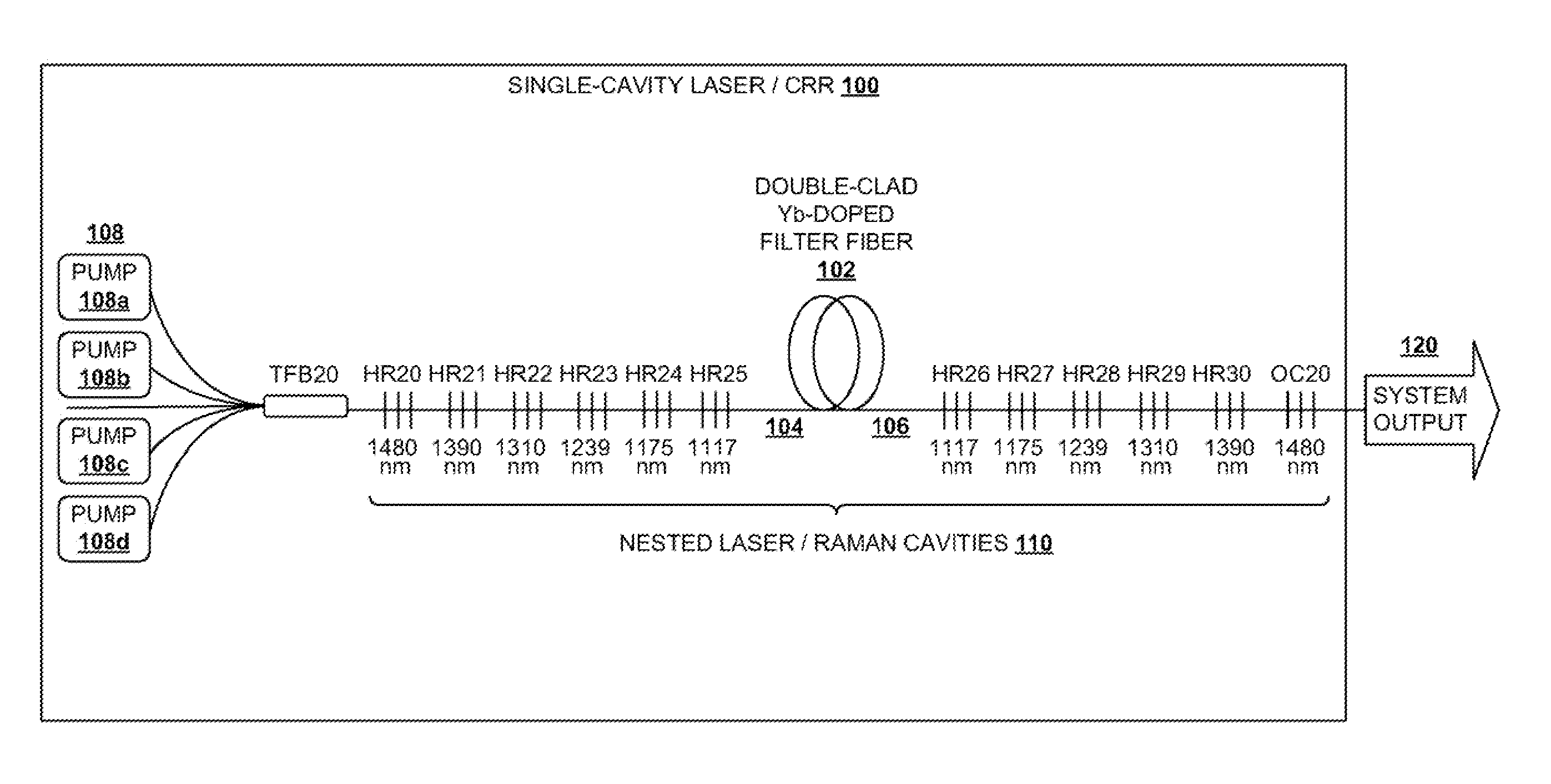
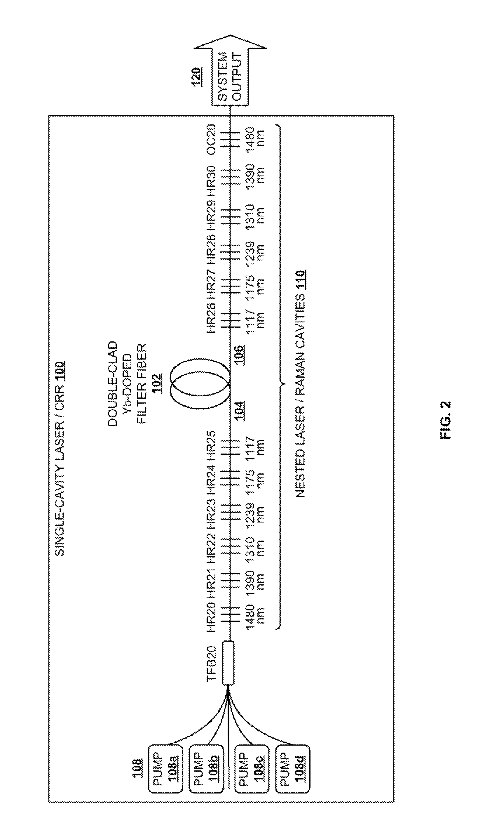
[0025]Aspects of the present invention are directed to systems and techniques in which a cascaded Raman resonator (CRR) is pumped at high powers, e.g., on the order of 20 W and above.

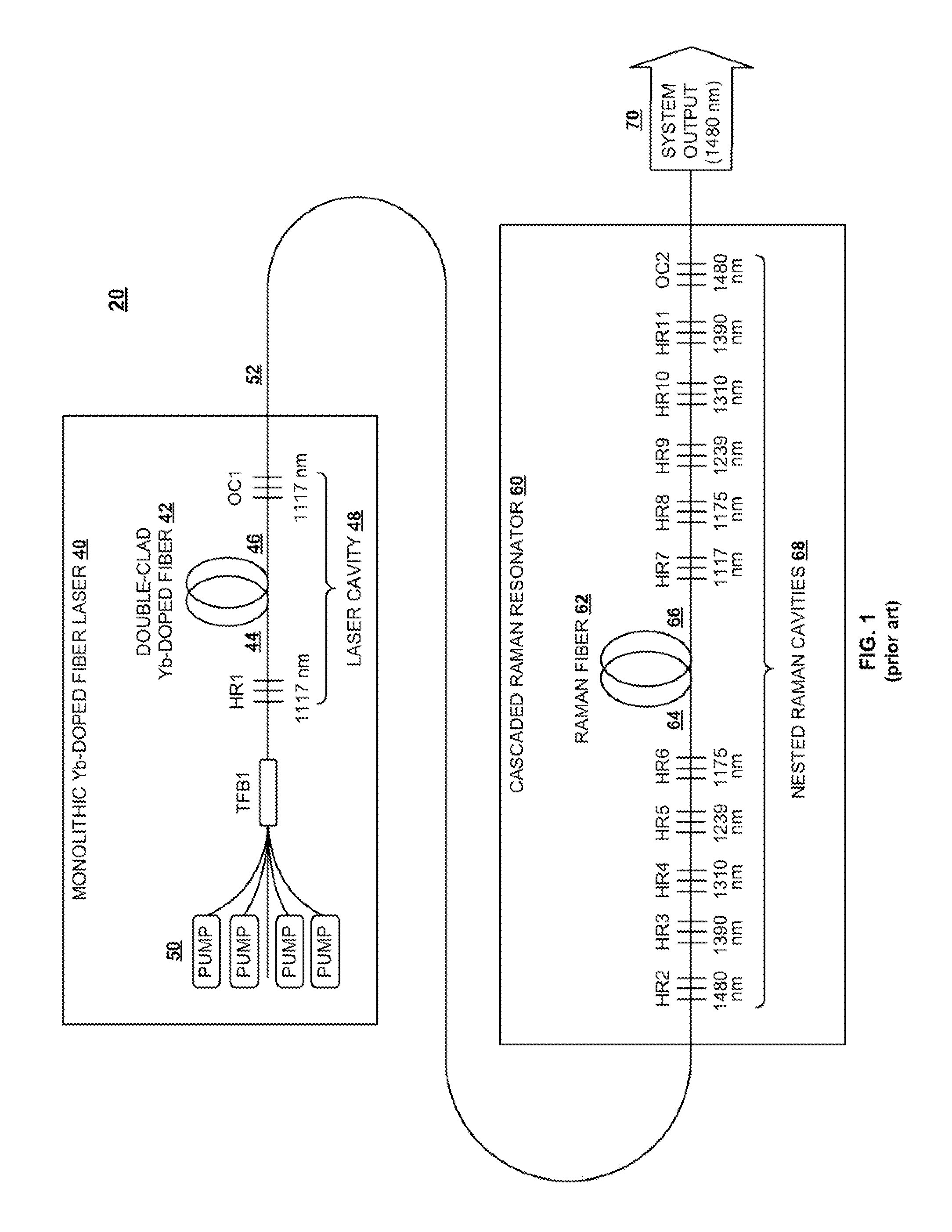
[0026]As discussed above, earlier designs suffered from instabilities arising from nested, coupled cavities. One possible solution is to use a master oscillator power amplifier (MOPA) configuration, in which the components of a monolithic high-power Yb fiber laser are separated into a low-power oscillator plus a high-power amplifier. The MOPA configuration allows the oscillator to be effectively isolated from the amplifier and cascaded Raman resonator using a suitable backward propagation prevention device, such as a fiber-coupled isolator or a filter wavelength division multiplexer (WDM), resulting in a system that is capable of reliable operation at 20 W continuous wave (CW) power. This approach is described in U.S. Provisional Patent Application Ser. No. 61 / 177,058, filed on May 11, 2009, which is ow...


PUM


Abstract

A light generation and amplification system includes a length of laser-active filter fiber having a refractive index profile that suppresses unwanted Stokes orders at wavelengths longer than a target wavelength and that has normal dispersion over its operating wavelength. A nested series of reflectors is provided at the fiber's input and output ends, and are configured to provide a nested series of Raman cavities, separated in wavelength by approximately the respective Stokes shifts. The first cavity in the series is a combined cavity that provides laser oscillation due to a combination of ionic gain and feedback at a selected first wavelength and that provides Raman gain to light at the first Stokes shift of the first wavelength when light at the first wavelength has an energy exceeding a Raman scattering threshold. The Raman cavities provide a stepwise transition between the first wavelength and the target wavelength.

Description

CROSS REFERENCE TO RELATED APPLICATION[0001]The present application claims the priority benefit of U.S. Provisional Patent Application Ser. No. 61 / 177,058, filed on May 11, 2009, which is owned by the assignee of the present application, and which is incorporated herein by reference in its entirety.BACKGROUND OF THE INVENTION[0002]1. Field of the Invention[0003]The present invention relates generally to optical fiber devices and methods, and in particular to an improved cascaded Raman fiber laser system based on a filter fiber.[0004]2. Background Art[0005]Cascaded Raman fiber lasers (CRFLs) are useful devices for generating laser outputs at wavelengths at which rare-earth ionic gain is not available. A CRFL provides a stepwise transition from a starting wavelength to a selected target wavelength. The stepwise transition is created through cascaded lasing of one or multiple Raman orders in a suitable Raman gain medium. A nested series of Raman cavities are created in the gain medium ...

Claims


Application Information

Patent Timeline
Patent Type & Authority Applications(United States)
IPC IPC(8): H01S3/30
CPCH01S3/0064H01S3/2375H01S3/0675H01S3/06754H01S3/06758H01S3/07H01S3/08086H01S3/094007H01S3/094042H01S3/09408H01S3/094084H01S3/09415H01S3/1618H01S3/302H01S3/06708H01S3/06733H01S3/094046H01S3/1608H01S3/0078
Inventor DIGIOVANNI, DAVID J.HEADLEY, CLIFFORD E.NICHOLSON, JEFFREY W.YAN, MAN F.
Owner OFS FITEL LLC
Why Eureka
Try Eureka