Fuel deoxygenator with porous support plate

Active Publication Date: 2010-11-25
RAYTHEON TECH CORP
View PDF58 Cites 44 Cited by
  • Summary
  • Abstract
  • Description
  • Claims
  • Application Information

AI Technical Summary

Problems solved by technology

The presence of dissolved oxygen in hydrocarbon liquid fuels may be objectionable because the oxygen supports oxidation reactions that yield undesirable by-products.
When aerated fuel is heated above 250° F. the dissolved oxygen initiates free radical reactions of the fuel resulting in deposits c

Method used


Image

  • Fuel deoxygenator with porous support plate
  • Fuel deoxygenator with porous support plate
  • Fuel deoxygenator with porous support plate

Examples


Embodiment Construction

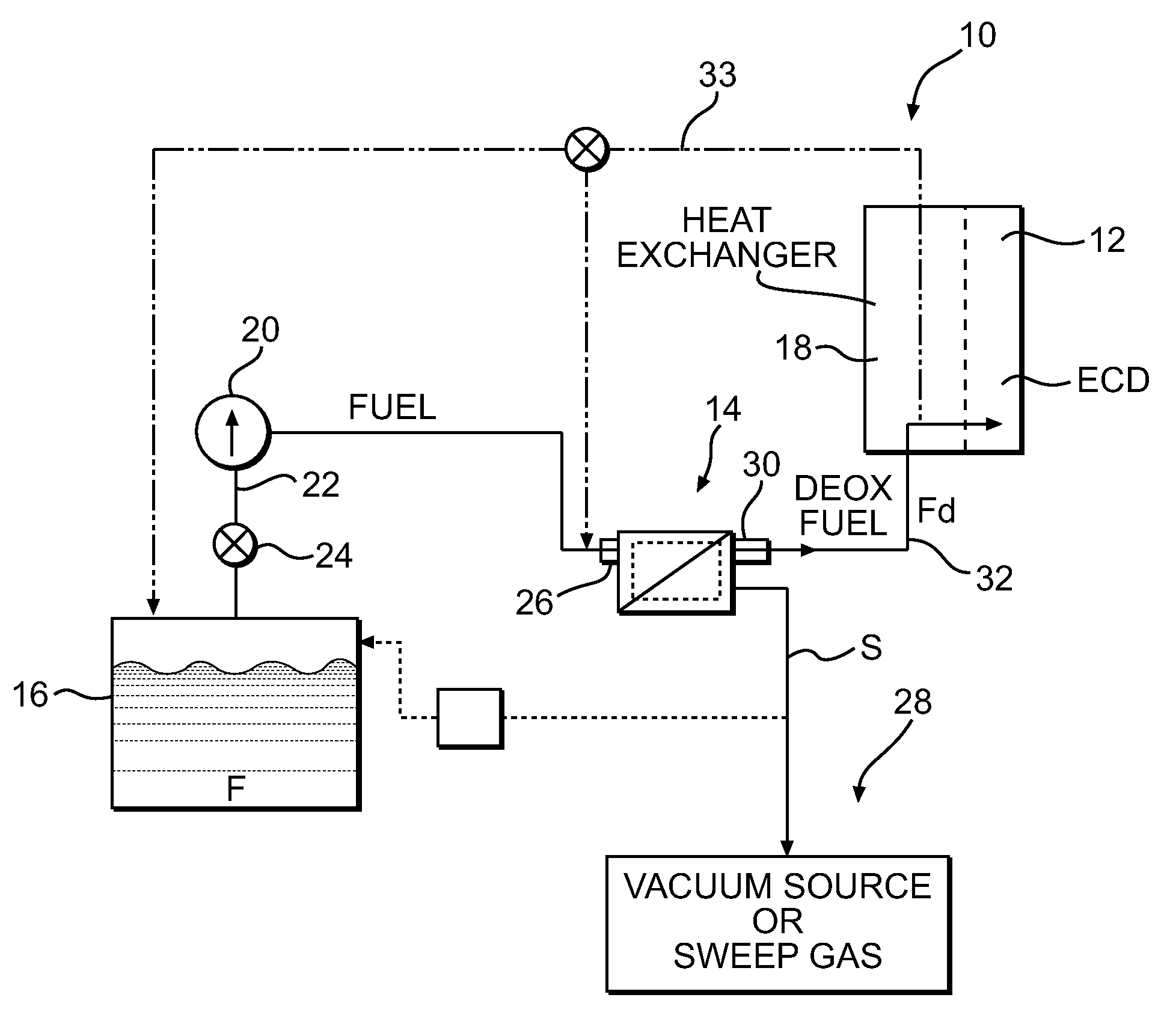
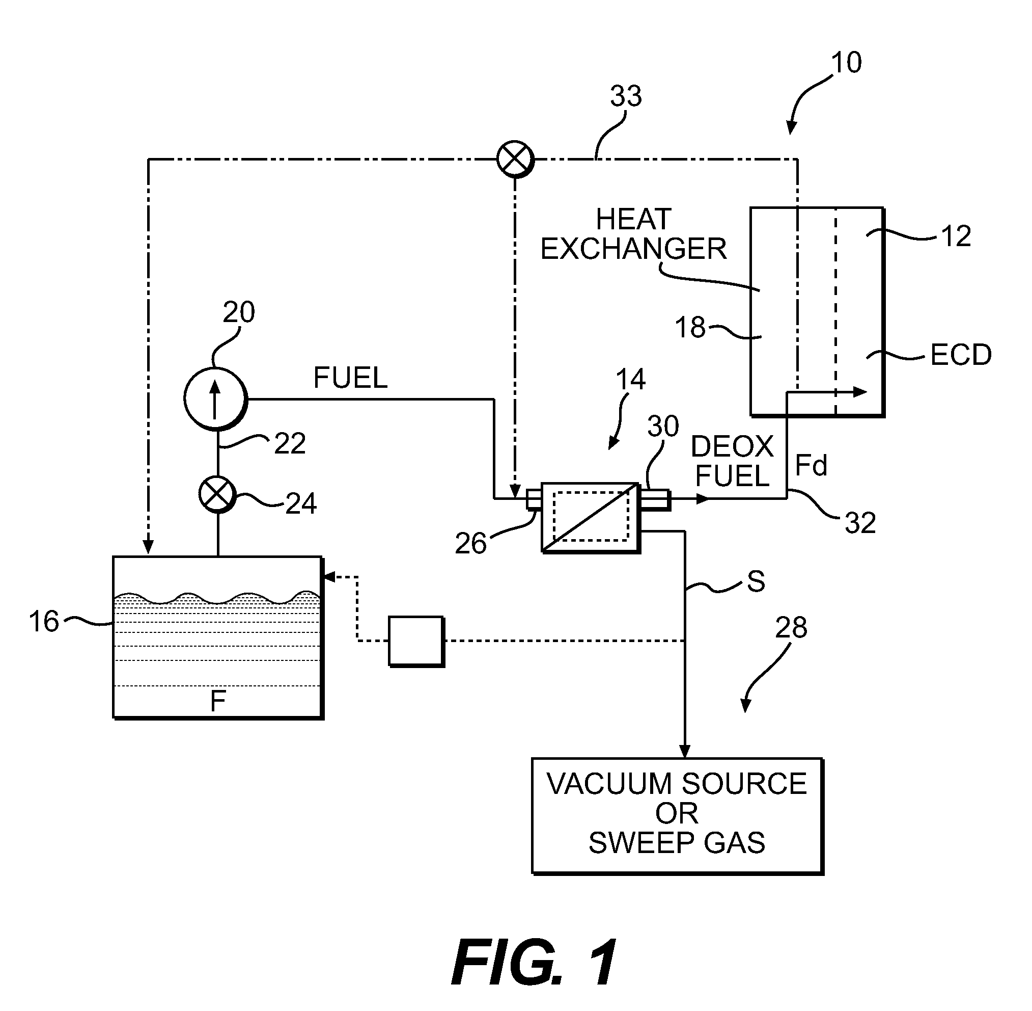
[0016]FIG. 1 illustrates a general schematic view of a fuel system 10 for an energy conversion device (ECD) 12 which demonstrates one example use of a fuel deoxygenator system 14 and is not intended to be limiting. The fuel deoxygenator system 14 receives liquid fuel F from a reservoir 16 such as a fuel tank. The fuel F is typically a liquid hydrocarbon such as jet fuel. The ECD 12 may exist in a variety of forms in which the fuel, at some point prior to eventual use for processing, for combustion, or for some form of energy release, acquires sufficient heat to support autoxidation reactions and coking if dissolved oxygen is present to any significant extent in the fuel.

[0017]One form of the ECD 12 is a gas turbine engine, such as in aircraft. Typically, the fuel also serves as a coolant for one or more sub-systems in the aircraft and becomes heated as it is delivered to fuel injectors immediately prior to combustion.

[0018]A heat exchange section 18 represents a system through which...


PUM

PropertyMeasurementUnit
Temperatureaaaaaaaaaa
Pore sizeaaaaaaaaaa
Densityaaaaaaaaaa

Abstract

A device for use in a fluid system includes a fuel channel for receiving fuel having dissolved gas therein. A gas permeable membrane supported by a porous support, the gas permeable membrane in communication with the fuel channel. A gas-removal channel adjacent the gas permeable membrane for receiving the dissolved gas from the fuel through the gas permeable membrane and the porous support.

Description

[0001]This invention was made with government support under Contract No.: FA8650-07-C-5062 with the Department of Air Force. The government therefore has certain rights in this invention.BACKGROUND[0002]The present application relates to degasification of liquids, and more particularly, to removal of gas from a liquid through a flow perturbation element within a fluid channel.[0003]Liquid fuel is often utilized in vehicles, such as aircraft, as a coolant for various systems. The presence of dissolved oxygen in hydrocarbon liquid fuels may be objectionable because the oxygen supports oxidation reactions that yield undesirable by-products. Dissolution of air in liquid fuel results in an approximately 70 ppm oxygen concentration at atmospheric pressure and equilibrium saturation conditions. When aerated fuel is heated above 250° F. the dissolved oxygen initiates free radical reactions of the fuel resulting in deposits commonly referred to as “coke” or “coking.” Coke may be detrimental ...

Claims


Application Information

Patent Timeline
IPC IPC(8): B01D53/22
CPCB01D19/0031B01D67/0006B01D69/125B01D2311/13Y02T10/126B64D37/34F02M31/16F02M33/00F02M37/0047B01D2323/26F23K2900/05082Y02T10/12B01D61/362
Inventor SCHMIDT, WAYDE R.CORDATOS, HARALAMBOSCULP, SLADE R.
Owner RAYTHEON TECH CORP
Why Eureka
Try Eureka