Absorber for a thermal solar collector and method for the production of such an absorber

a technology of absorbers and solar collectors, applied in solar heat devices, solar heat collectors with working fluids, lighting and heating apparatus, etc., can solve problems such as poor quality welded joints, reduce heat input into the absorber surface during welding with diode laser using the cw method, and reduce the effect of heat inpu

Inactive Publication Date: 2010-11-25
LINK ANDREAS
View PDF8 Cites 9 Cited by
  • Summary
  • Abstract
  • Description
  • Claims
  • Application Information

AI Technical Summary

Benefits of technology

[0031]Owing to the fact that the welded joint, which can, in particular, also be present in bent regions of the tube, is interrupted in the inventive absorber, there is an increase in the thermal contact area between sheet and tube by comparison with connections which only have spot welds produced by means of pulsed lasers, and this improves the transfer of heat. Moreover, the quality of the connection can be improved, since the welded joint of the inventive absorber can be produced by means of a continuously operating laser, the path to the weld seam to be formed being temporarily cleared and interrupted. There is thus no need for any actual interruptions of the welding process such as, for example, when welding with a pulsed laser beam. Welded joints of poorer quality arise upon applying and removing the welding set, that is to say upon switching the laser beam on and off with a pulsed laser, than is the case with a continuously operating laser.
[0062]In a particular refinement of the inventive method, the thermal fluid tube and / or the absorption sheet are under mechanical stress during welding. A particularly good welding result, and a particularly good durability of the product produced can be attained by means of a suitable mechanical stressing.

Problems solved by technology

Welded joints of poorer quality arise upon applying and removing the welding set, that is to say upon switching the laser beam on and off with a pulsed laser, than is the case with a continuously operating laser.

Method used


Image

  • Absorber for a thermal solar collector and method for the production of such an absorber
  • Absorber for a thermal solar collector and method for the production of such an absorber
  • Absorber for a thermal solar collector and method for the production of such an absorber

Examples


Embodiment Construction

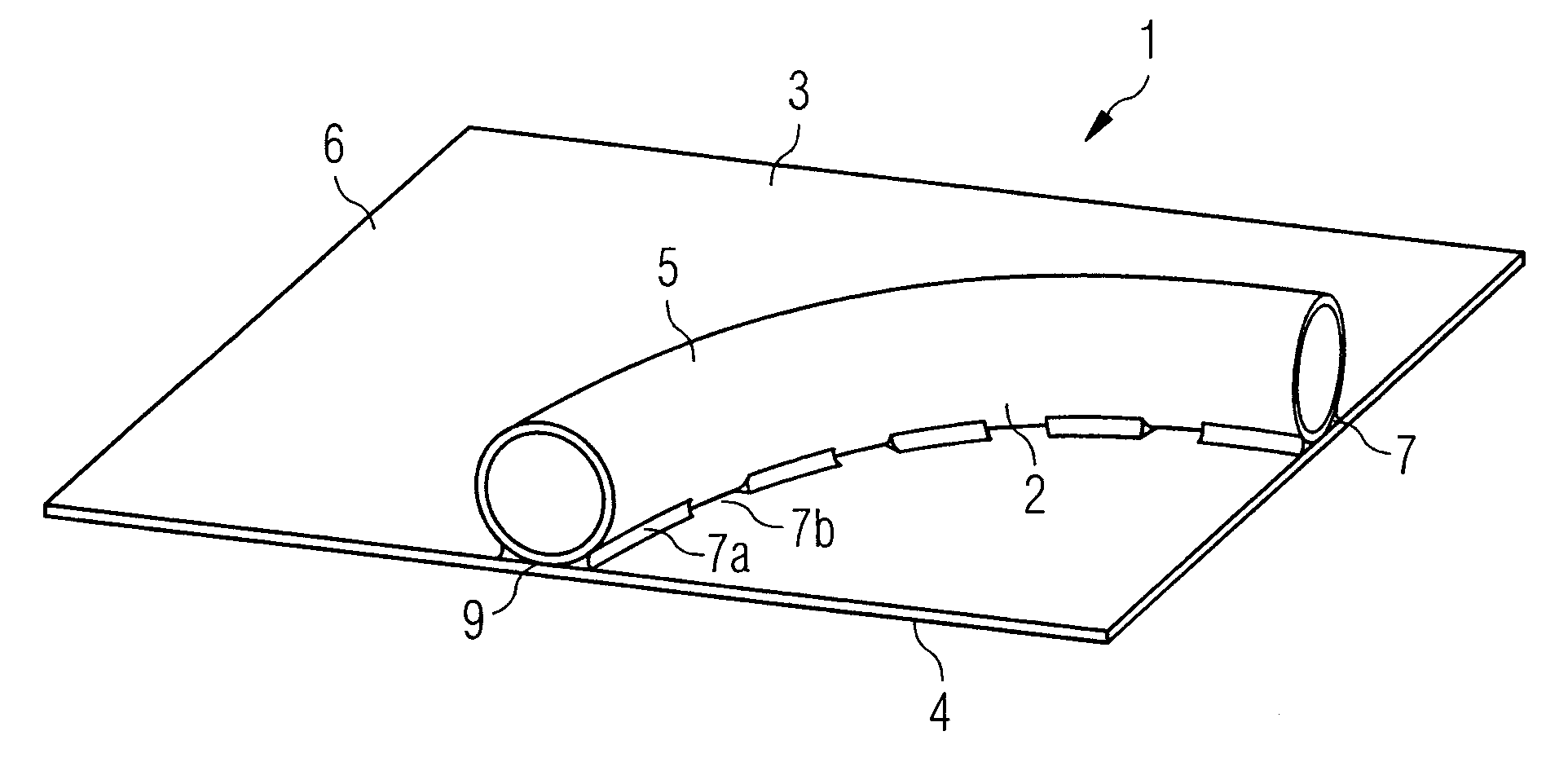
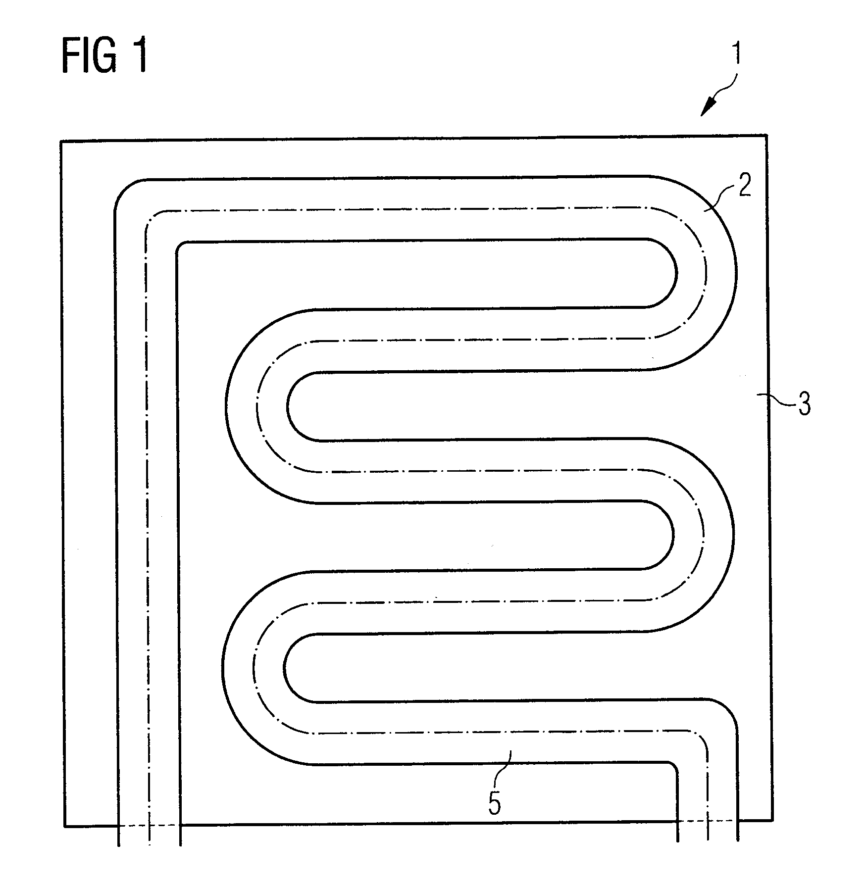
[0072]An inventive absorber is shown in FIG. 1 in a greatly simplified illustration.

[0073]The absorber 1 comprises as essential components an absorber sheet 3 with a meandering thermal fluid tube 5 welded thereon.

[0074]On its surface averted from the thermal fluid tube 5, the absorber sheet 3 has a highly selective coating that absorbs the radiant energy of the sun and converts it into heat. The heat is finally output to a thermal fluid, for example water or a water / glycol mixture, that flows through the thermal fluid tube 5 and transports the heat to its destination.

[0075]The absorber sheet 3 and the thermal fluid tube 5 welded thereon are generally arranged in a protective housing that, at least in the region of the absorbing surface of the absorber sheet 3, is configured to be transparent in such a way that it allows the insolation to pass largely unhindered. The housing itself is not illustrated in FIG. 1, for the sake of clarity.

[0076]By way of example, copper sheet with copper...


PUM

PropertyMeasurementUnit
thicknessaaaaaaaaaa
melting temperaturesaaaaaaaaaa

Abstract

An absorber (1) for a thermal solar collector, comprising an absorber sheet (3) and at least one thermal fluid tube (5) that is connected in a thermally conducting fashion to the absorber sheet (3) and is connected to the absorber sheet (3) by means of a welded joint, is characterized in that the welded joint is formed from a number of linearly extended weld seam sections arranged sequentially along the thermal fluid tube (5) and respectively separated from one another by a section without weld seam, the direction of the linear extent of the weld seam sections corresponding to the axial direction of the extent of the thermal fluid tube.

Description

BACKGROUND OF THE INVENTION[0001]1. Field of the Invention[0002]The present invention relates to an absorber for a thermal solar collector having an absorber sheet and at least one thermal fluid tube connected in a thermally conducting fashion to the sheet. The present invention also relates to a method for producing an absorber for a thermal solar collector.[0003]2. Description of the Related Art[0004]A thermal solar collector absorbs the radiation of the sun and converts this into heat. The collected heat is transferred to a thermal fluid as transport means that transports the heat to its point of destination.[0005]The core of a thermal solar collector is the absorber. This comprises a specifically coated sheet, called an absorber sheet below, and at least one tube connected in a thermally conducting fashion to the sheet. When the sheet is heated because of insolation, the heat is passed on to the thermal fluid flowing through the tubes. A circulation of the thermal fluid can then...

Claims


Application Information

Patent Timeline
Patent Type & Authority Applications(United States)
IPC IPC(8): F24J2/48B23K26/00F24S10/70F24S10/75
CPCF24J2/26Y02E10/44F28F2275/067F24S10/75
Inventor LINK, ANDREAS
Owner LINK ANDREAS
Why Eureka
Try Eureka