Normally open type piezoelectric element driven metal diaphragm control valve

a piezoelectric element and control valve technology, applied in the direction of diaphragm valves, engine diaphragms, operating means/releasing devices of valves, etc., can solve the problems of difficult to ensure the transmission of generating force damage the like, so as to reduce the weight or force applied to the metal diaphragm, the effect of accurate flow rate control

Active Publication Date: 2010-11-25
FUJIKIN INC
View PDF13 Cites 24 Cited by
  • Summary
  • Abstract
  • Description
  • Claims
  • Application Information

AI Technical Summary

Benefits of technology

[0021]A normally open type piezoelectric driven metal diaphragm control valve of the present invention exhibits excellent effects as follows:
[0022](1) A normally open type piezoelectric driven metal diaphragm control valve in accordance with the present invention is equipped with a preload mechanism, which applies an upward compressive force constantly to the piezoelectric element so as to make it possible that the certain compressive force is constantly applied to the piezoelectric element through mediation of preload even when the actuator box, which accommodates the piezoelectric element, is in an expanded state due to thermal expansion, for example, which may occur when the control valve is in use under high temperature conditions. As a result, accurate flow rate control can be achieved by the piezoelectric element driven metal diaphragm control valve of the present invention because the generating force is transmitted surely and smoothly to the metal diaphragm at the time when the piezoelectric element is elongated.
[0023](2) The piezoelectric element driven metal diaphragm control valve, in accordance with the present invention, has its piezoelectric element compressed upwardly all the time by the preload mechanism and, therefore, can remove the force of weight of the piezoelectric element exerted to the metal diaphragm. This feature makes the weight or force applied to the metal diaphragm lighter, and also reduces the load to be applied to the metal diaphragm at the time when the metal diaphragm departs from the valve seat due to the elasticity of the metal diaphragm, thus preventing deterioration of the metal diaphragm and improves the life of the metal diaphragm.
[0024](3) A piezoelectric element driven metal diaphragm control valve, in accordance with the present invention, has a preload spring of a preload mechanism that presses the piezoelectric element at all times, wherein the preload spring is provided around the actuator box, and the compressive force applied to the piezoelectric element of the piezoelectric element driven metal diaphragm control valve can be adjusted by means of a preload adjustment nut screwed to a No. 2 preload jig positioned outside the actuator box. This feature of the invention does not require that the actuator box, and the like, be upsized even when the preload spring is selected to have large elasticity. Furthermore, the strength of the compressive force applied to the piezoelectric element can be freely adjusted by means of the preload adjustment nut without having to disassemble the control valve.
[0025](4) A piezoelectric element driven metal diaphragm control valve of the present invention is provided with a No. 2 preload jig of the preload mechanism, a preload adjustment nut and a preload spring disposed around the actuator box. This feature of the invention thus allows assembly of the piezoelectric element driven metal diaphragm control valve to be achieved relatively simply and easily.
[0026](5) A piezoelectric element driven metal diaphragm control valve, in accordance with the present invention, is provided with a diaphragm presser installed on an upper face side of the metal diaphragm and a piezoelectric element provided with a conical spring mechanism that allows the elongation of the piezoelectric element to be absorbed at the time when the metal diaphragm makes contact with the valve seat, and so that a prescribed amount of thrust is applied to the valve seat and to the part or portion (i.e., a seat part) of the metal diaphragm making contact with the valve. Thus, the conical spring mechanism absorbs elongation of the piezoelectric element once the metal diaphragm makes contact with the valve seat thereby preventing the metal diaphragm and the valve seat from being damaged due to a large generating force generated by the piezoelectric element because the conical spring mechanism ensures that such a force is not being directly applied to the seat part.

Problems solved by technology

This configuration makes adjustment difficult, and also causes disadvantages in that the metal diaphragm, the valve seat, and the like, might be damaged because a large generating force generated by the piezoelectric element is applied to the seat part.
However, even with a control valve provided with a conical spring, there remain some disadvantages which need to be solved.
This clearance space makes it difficult for the generating force to be transmitted surely and smoothly to the metal diaphragm at the time when the piezoelectric element is elongated, thus making accurate flow rate control impossible or difficult to achieve.
However, such a control valve has not yet been developed to this date.
Also, another disadvantage with a control valve provided with a returning elastic body and a load spring inside the valve is that it is required that the control valve needs to be dismantled in order to replace the returning elastic body or the load spring, which are stored inside the control valve with another replacement returning elastic body or load spring, or to adjust the elasticity of the returning elastic body or load spring.
Assembling and disassembling of the control valve are very time-consuming.

Method used


Image

  • Normally open type piezoelectric element driven metal diaphragm control valve
  • Normally open type piezoelectric element driven metal diaphragm control valve
  • Normally open type piezoelectric element driven metal diaphragm control valve

Examples


Embodiment Construction

[0057]The preferred embodiment of the present invention is described in detail hereinafter with reference to the drawings.

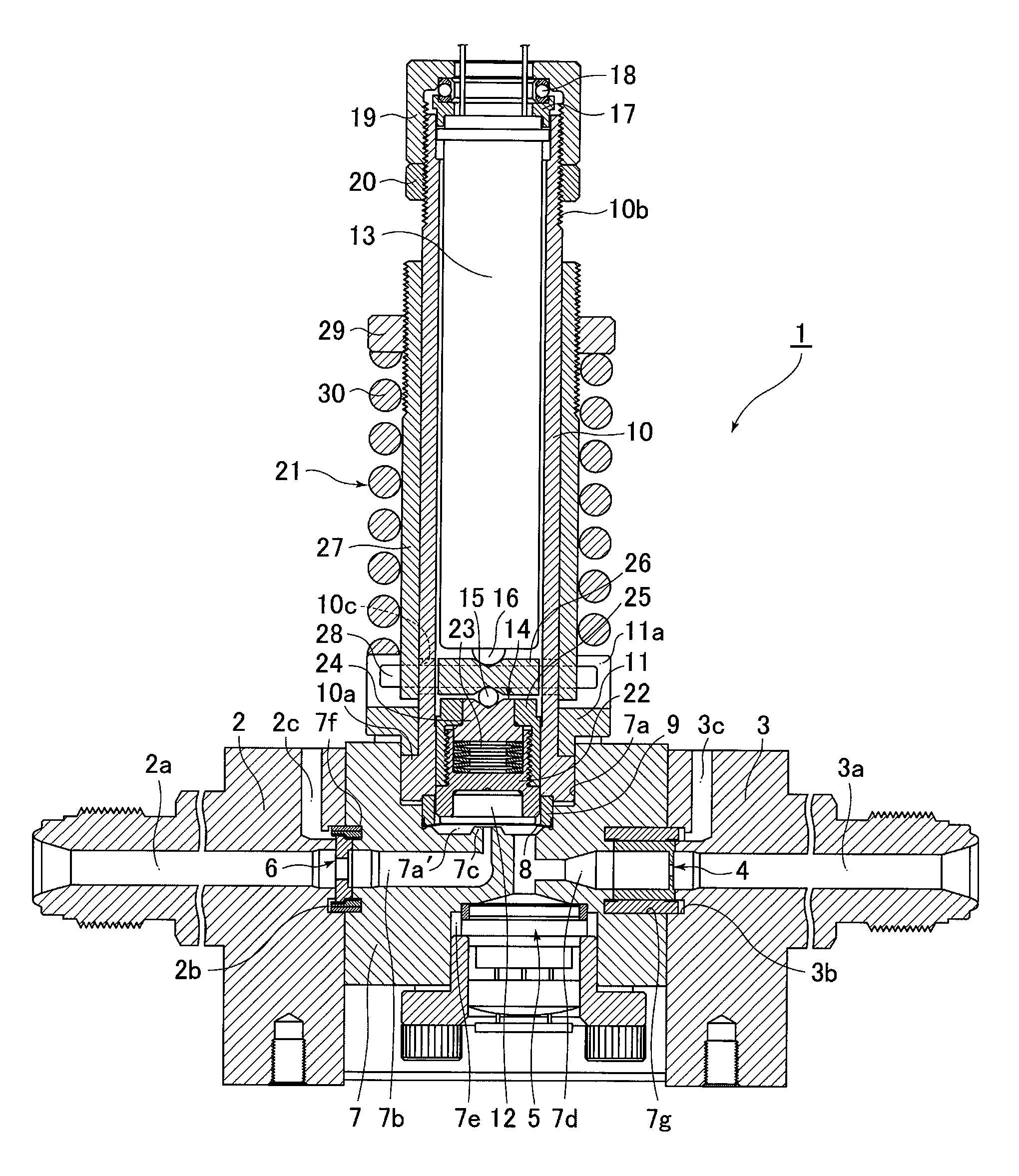
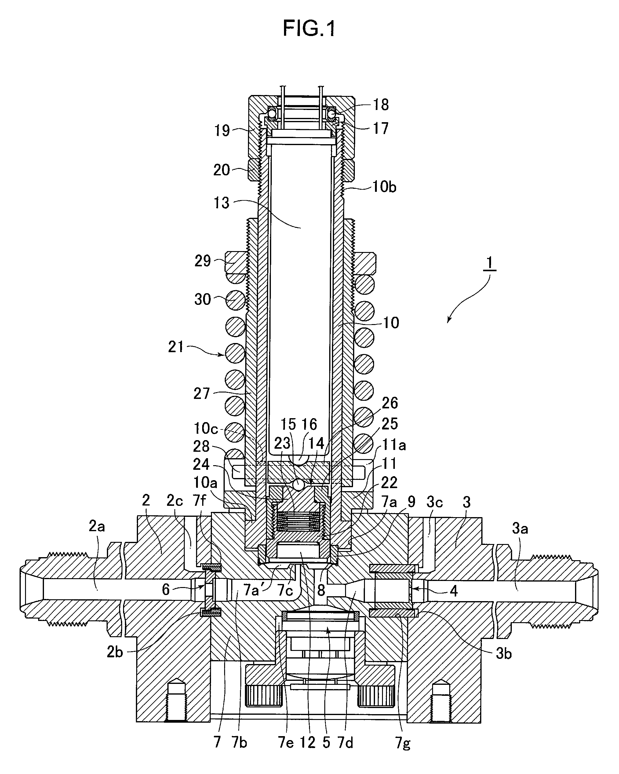
[0058]FIG. 1 illustrates a normally open type piezoelectric element driven metal diaphragm control valve 1 in accordance with a preferred embodiment of the present invention, which is used as a control valve for a pressure type flow rate control apparatus. The aforementioned pressure type flow rate control apparatus is constituted to include a piezoelectric element driven metal diaphragm control valve 1, an inlet side block 2 connected to an upstream side of the piezoelectric element driven metal diaphragm control valve 1, an outlet side block 3 connected to the downstream side of the piezoelectric element driven metal diaphragm control valve 1, an orifice 4 used for flow rate control that is provided on the downstream side of the piezoelectric element driven metal diaphragm control valve 1, a pressure sensor 5 for detecting upstream side pressure of the orifice ...


PUM


Abstract

A control valve has a body that forms a valve chamber and a valve seat, a metal diaphragm installed inside the valve chamber and making contact with and departing from the valve seat, an actuator box fixed to the side of the body, a piezoelectric element installed inside the actuator box to thrust the metal diaphragm through mediation of a metal diaphragm presser by elongating downward when voltage is applied, a conical spring mechanism that absorbs elongation of the piezoelectric element at the time when the metal diaphragm makes contact with the valve seat and a prescribed thrust is applied to the valve seat and the like, and a preload mechanism that applies upward compressive force to the piezoelectric element all the time wherein the compressive force applied to the piezoelectric element is externally adjustable.

Description

[0001]This is a National Phase Application in the United States of International Patent Application No. PCT / JP2006 / 323050 filed Nov. 13, 2006, which claims priority on Japanese Patent Application No. 2006-009625, filed Jan. 18, 2006. The entire disclosures of the above patent applications are hereby incorporated by reference.FIELD OF THE INVENTION[0002]The present invention relates to improvements in a normally open type piezoelectric element driven metal diaphragm control valve to be used mainly as a control valve for a pressure type flow rate control apparatus or as a control valve for a flow rate control part of a mass flow controller that is provided with a gas control line for semiconductor manufacturing facilities, and the like. More particularly, the present invention is concerned with a normally open type piezoelectric element driven metal diaphragm valve with which accurate and stable flow rate control can be achieved even under high temperature conditions in which high tem...

Claims


Application Information

Patent Timeline
Patent Type & Authority Applications(United States)
IPC IPC(8): F16K31/02
CPCF16K7/14F16K24/04F16K51/02F16K31/007F16K31/004F16K31/02
Inventor MATSUMOTO, ATSUSHIHIRATA, KAORUDOHI, RYOUSUKEIKEDA, NOBUKAZUNISHINO, KOUJI
Owner FUJIKIN INC
Why Eureka
Try Eureka