Tagged multi line address driving

a multi-line address and driving technology, applied in the direction of instruments, electric digital data processing, cathode-ray tube indicators, etc., can solve the problems of limited display size of pmoled display devices, increased harmful properties of wires, and increased complexity, so as to reduce complexity

Inactive Publication Date: 2010-11-25
DIALOG SEMICONDUCTOR GMBH
View PDF6 Cites 27 Cited by
  • Summary
  • Abstract
  • Description
  • Claims
  • Application Information

AI Technical Summary

Benefits of technology

[0069]A principal object of the present invention is to realize a system for an FPD with a very economic multi line addressing scheme for OLED displays and essentially reduced complexity.

Problems solved by technology

In addition, the display size of a PMOLED display device is limited by this matrix structure.
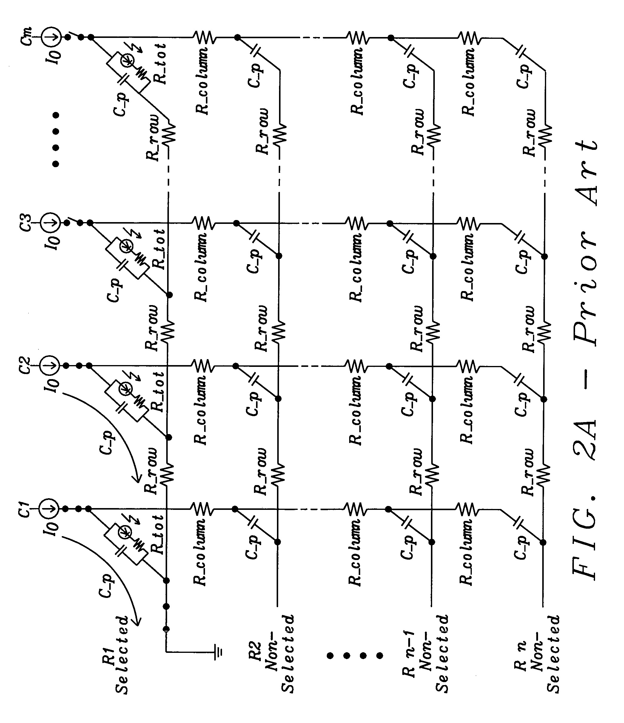
The larger the matrix becomes the longer the wires get with an increase of their harmful properties, such as resitivity losses on wires and parasitic capacitances between lines responsible e.g. for perturbing crosstalk effects.
Although the PMOLED display has a simple configuration and an advantage in terms of cost, the difficulty in realizing a display with large size and high brightness as well as low power consumption and high lifetime is limiting its use.
An AMOLED display device has problems however in that variations in component characteristics of the pixel circuit may exist and thus brightness of each pixel which make up the display screen may vary.
However, OLED technology in very large-screen or huge-screen display applications is currently still on its way into the mass market; examples include huge time-table displays at train stations, in airports, or at harbors, or displays for large marketing advertisements and mass-public informational purposes including those displaying share prices in stock exchanges, and huge indoor or even outdoor stadium displays.
Therefore, the more light output needed, the more current has to be fed to the pixels which on the other hand is detrimental to the lifetime of the pixels.
However, the PMOLED displays used in many modern applications encounter several common issues when the displays become larger and especially if they should also display video streams with moving pictures.
These issues include sensible higher power consumption, thus an elevated operating temperature and, the larger they get a slower frame response with poorer contrast.
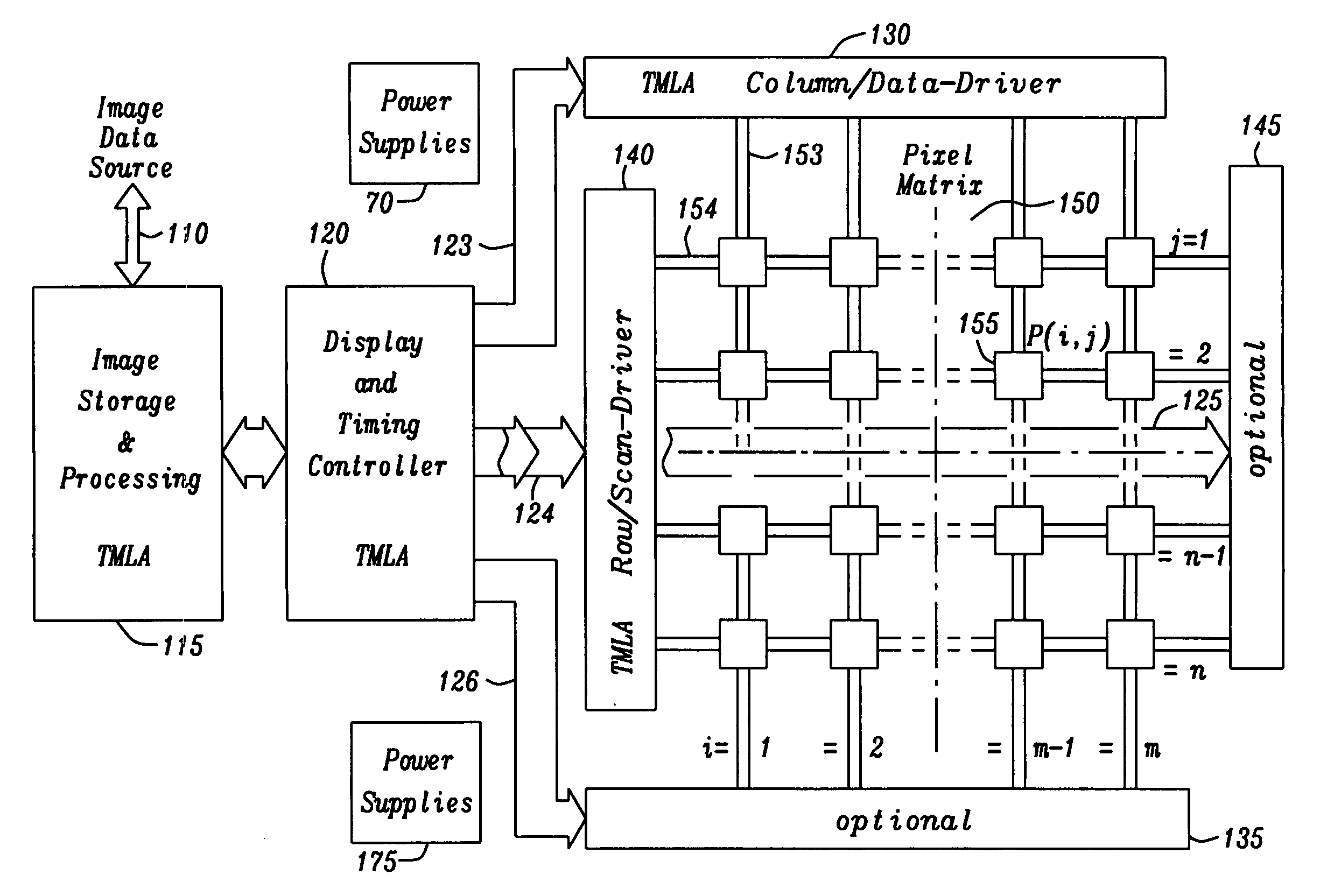
Having large numbers of vertical Column lines results in large currents to charge many OLED pixels at once.
Preferably is, however, to allow individual pixels to remain on for a longer time and hence reduce the overall drive level.
In a PMOLED matrix configuration the brightness can vary across the area of a display and also with operation time, temperature, and age, making it difficult to predict how bright a pixel will appear when driven by a voltage.
Especially in color displays the accuracy of color representations may be affected.
Another major challenge with using PMOLED in high resolution displays is that the operating lifetime is limited, as already adumbrated.
Modern MLA schemes have been further expanded and continuously developed into the Consecutive MLA (CMLA) scheme, a rather complex matrix decomposition method combining MLA and Single Line Addressing (SLA) techniques described in the WIPO Patent Application (WO / 2007 / 079947 to Xu et al.) cited below, which however not in all cases delivers optimal solutions, sometimes even augmenting the number of necessary charging operations.
Total Matrix Addressing (TMA) from U.S. Patent Application (2008 / 0246703 to Smith et al.) also cited below, despite and eventually because of its need of substantial processing power, is also not very satisfactory concerning overall efficiency in terms of power saving.
As can already be seen from the above the goal to both get the benefits of MLA schemes for FPD driving and at the same time limit the processing power requirements in favor of a low power consumption and augmented life-time of the whole FPD product is not easy to attain, a multitude of MLA schemes have been proposed with varying success given the surplus expenses needed.
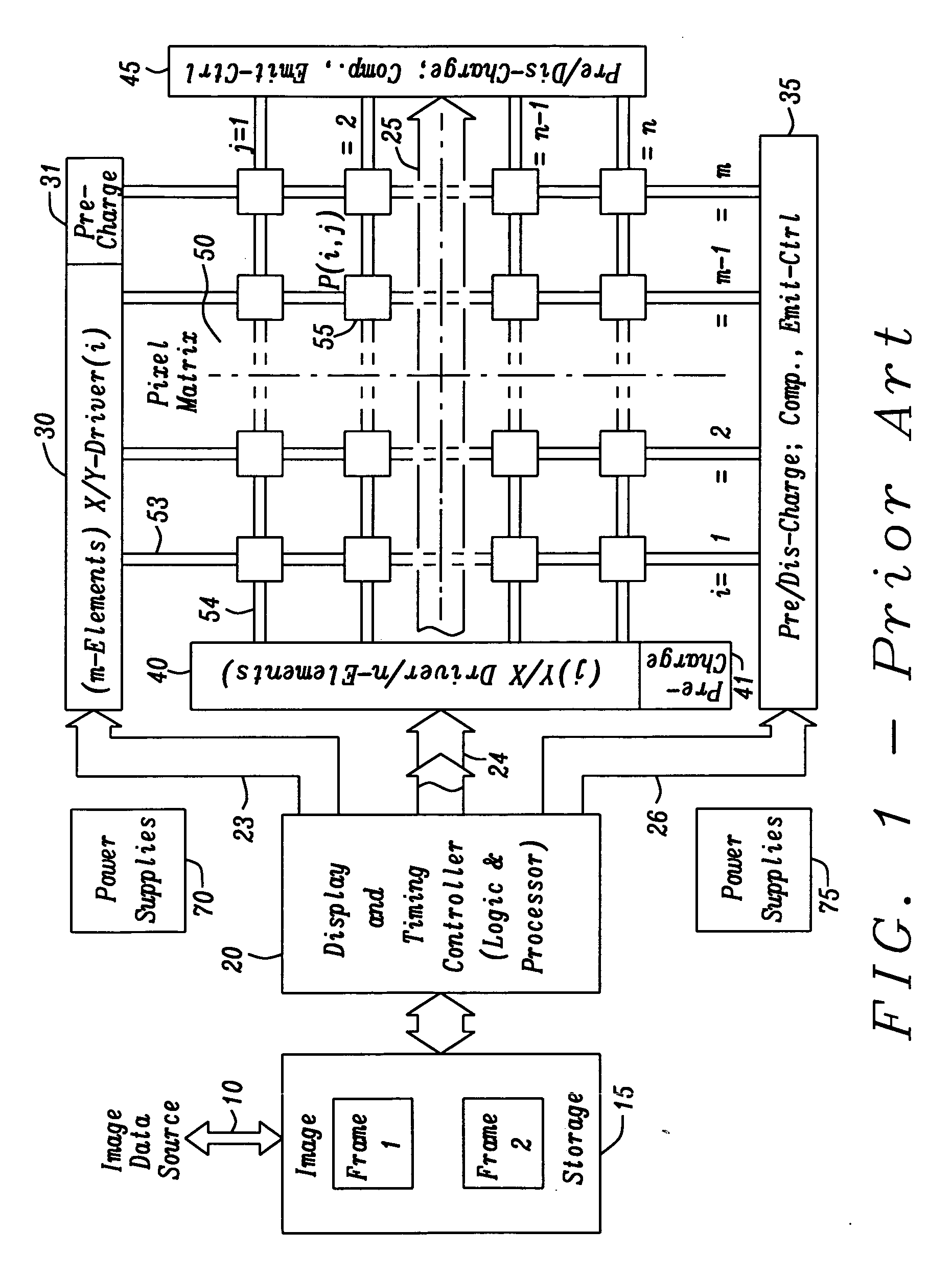
Problems encountered in actual pixel layouts include, for example, contact between pixel electrodes and peripheral circuitry, stability of holding capacitances, and transistor turn-off currents.
However, in actual reality, there arises the problem that a display unevenness of the display picture is caused due to the non-uniformity of the threshold voltage and the charge drift mobility of the driver transistor.
However, these TFTs, after prolonged use, will exhibit a threshold voltage shift.
As a result, the luminance of each diode will not have the same correspondence relation as the received pixel data, which in turn results in an uneven frame display.
However, recent OLED panels tend to be developed in high resolution and large size.
However, the switching TFT has small current as it is turned on, and thus it needs longer compensation time, which will result in an irregular operation of the switching TFT and disability of the compensation mechanism.
However, with the circuit design of a conventional voltage compensation arrangement, it is essential that the nodes connected to both X and Y line nodes have a stable voltage state during the “data writing” stage, otherwise, a charge sharing issue will be generated at the frame display stage.
Accordingly, the conventional voltage compensation arrangement is apt to exhibit the drawback that the the node X does not reach a stable voltage state for canceling the threshold voltage of the driving TFT to be compensated due to inadequate time.
As a result, the charge sharing issue is generated and the display luminance can not reach the predicted luminance in correspondence with the pixel voltage.
The pixel circuit of the current programming method produces a long data programming time since it must charge and discharge parasitic capacitances generated at the data line.
Such a leakage current is small in the ideal device, but will be significantly larger if a defect is present.
However these approaches use often solutions, which are somewhat technically complex and therefore also expensive in production.

Method used


Image

  • Tagged multi line address driving
  • Tagged multi line address driving
  • Tagged multi line address driving

Examples


Embodiment Construction

[0097]The preferred embodiments disclose novel realizations for display controller and driver circuits for FPDs solving the problem of inherent high power consumption of OLED displays and unwanted elevated power consumption by additional MLA scheme calculation operations and are described here by one exemplary showcase circuit of an FPD and especially by a new method of operation according to this invention. The higher the resolution of an FPD with a certain size, the more lines, i.e. rows and columns does it contain. Inherent high power consumption of higher resolution (high-res) OLED displays, especially troublesome for PM types, but to a lesser extent also found within AM types, not only reduces the operating time of portable, battery powered appliances but also reduces the lifetime of OLED displays by heating up the OLED pixel diodes. The reason for this is that in conventional SLA modes the full luminance driving current must be injected into each OLED pixel diode within only o...


PUM


Abstract

A circuit for a flat panel display includes an image data storage and processing block, a display and timing controller block, an image pixel matrix containing a multitude of row and column arranged pixel elements, one or more controlled row and column driver blocks, and a tagged multi line addressing (TMLA) pixel element display operation. That TMLA operation comprises a decomposition of image data by searching all lines of an image for groups of identical lines by tagging each of these lines with a unique code and thus decomposes image data into multi line and single line domain data in such a way, that lines with matching tags, indicating their common and identical contents, are outputted as image data into related groups of the multi line domain with no left over residual image data and thus the related groups in the single line domain data are all zeroes.

Description

RELATED APPLICATIONS[0001]This application is related to the following US patent applications:[0002]DS08-013, titled “Back to Back Pre-charge Scheme”, Ser. No. ______, filing date ______.[0003]DS08-014, titled “Advanced Mult Line Addressing”, Ser. No. ______, filing date ______.[0004]DS08-015, titled “Extended Multi Line Address Driving”, Ser. No. ______, filing date ______.[0005]The contents of all three of these applications are hereby incorporated by reference in their entirety.BACKGROUND OF THE INVENTION[0006](1) Field of the Invention[0007]The present invention relates in general to image display devices, display panels, and driving methods thereof implemented within display driver circuits, and particularly to the drive circuitry of matrix large-screen and high resolution organic light-emitting diode (OLED) displays, especially circuits used in LED drivers manufactured as semiconductor integrated circuits. Even more particularly, this invention relates to a multi line address ...

Claims


Application Information

Patent Timeline
Patent Type & Authority Applications(United States)
IPC IPC(8): G09G5/36G09G5/00
CPCG09G3/3216G09G2330/021G09G2310/0205
Inventor SOMERVILLE, ALANJONES, KEVIN
Owner DIALOG SEMICONDUCTOR GMBH
Why Eureka
Try Eureka