This helps you quickly interpret patents by identifying the three key elements:
Problems solved by technology
Method used
Benefits of technology
Benefits of technology
[0006]An object of the present invention is hence to improve efficiency of lighting systems. This is achieved in different aspects as specified below.
[0007]Hence, in a first aspect, there is provided a lighting system that comprises a light emitting device capable of emitting first light having a first peak wavelength and a fluorescent material structure capable of absorbing at least part of the first light and emitting second light having a second peak wavelength. A first dichroic mirror structure capable of reflecting at least part of the first light and transmitting at least part of the second light is arranged in relation to the light emitting device and the fluorescent material structure to facilitate for at least part of the first light in reaching the fluorescent material structure. A second dichroic mirror structure capable of reflecting at least part of the second light and transmitting at least part of the first light is arranged in relation to the light emitting device and the fluorescent material structure to prevent at least part of the second light from reaching the light emitting device.
[0008]That is, by providing such an arrangement of dichroic mirrors that reflects and transmits the first and second light it is possible to obtain a mix of light from the system having a relatively small etendue. In comparison with prior art systems, there is no need to cover the light-emitting device with the fluorescent material. Rather, the fluorescent material may be placed apart from the light-emitting device. Thereby, the light that is generated by the fluorescent material does not need to pass through the fluorescent material, which leads to a number of advantages. For example, an improved efficiency in the conversion of first light to second light. It is also advantageous because it is much easier to manufacture such a fluorescent material, due to the fact that there is no need to accurately control a layer thickness. The efficiency is even further improved in that the arrangement of the dichroic mirrors prevent second light from being absorbed by the light-emitting device. Furthermore more light will be emitted in the desired direction, that is a certain degree of collimation is obtained.
Problems solved by technology
However, a drawback with such phosphor covered LED dies is that a lot of the light that is generated exits the phosphor layer in a wrong direction and falls onto the blue die and is absorbed.
This may result in an undesired discoloration of the light beam in the far field.
Another drawback of such devices is that they typically have a large etendue.
Although, some degree of collimation can be regained by adding, e.g., a so-called Brightness enhancement foil (BEF), such solutions will reflect some of the light in the direction of the source and hence they are not very efficient.
Method used
Image
Click on the blue label to locate the original text in one second.
Reading with bidirectional positioning of images and text.
Examples
first embodiment
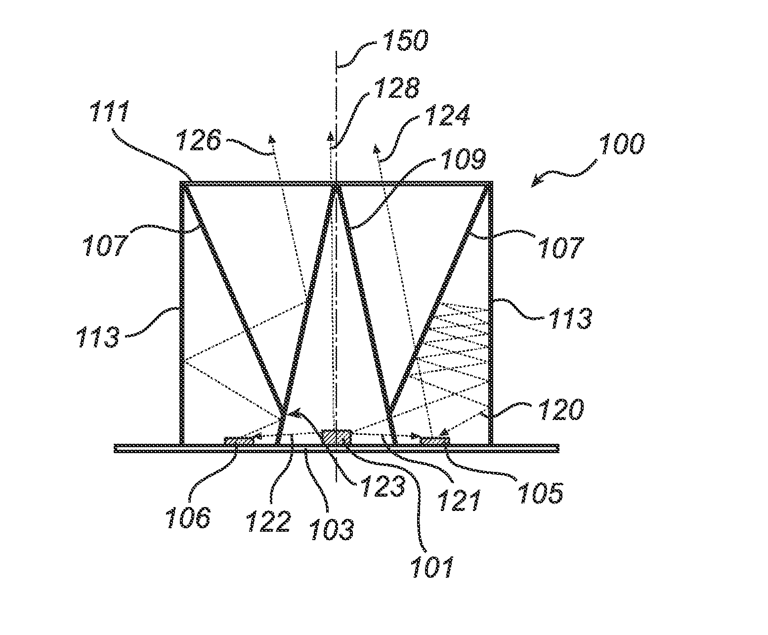
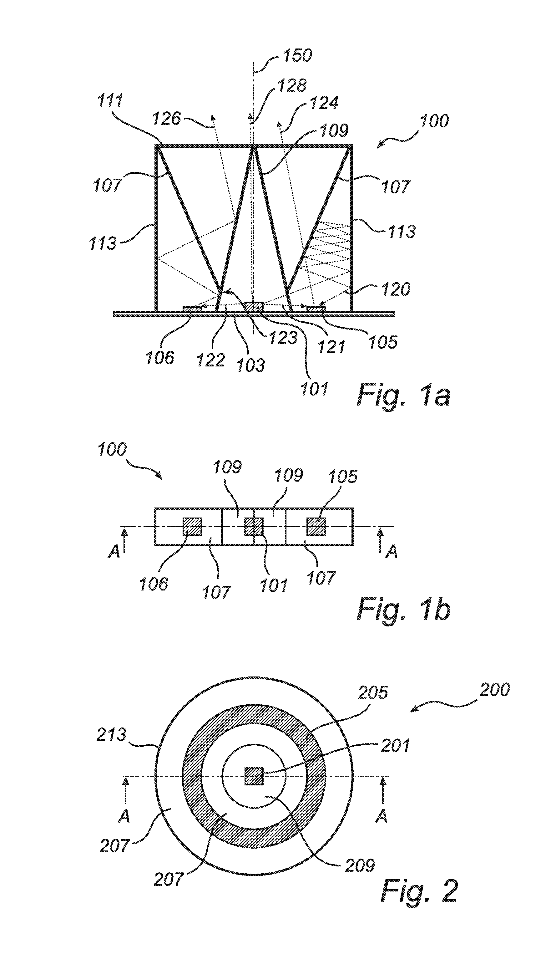
[0030]Turning now to FIGS. 1a and 1b, a lighting system 100 will be described. FIG. 1a is a side view in cross section AA and FIG. 1b is a view from above.
[0031]A light emitting diode (LED) 101, capable of emitting blue light 120, 121, 122, 128, is mounted on a substrate 103, on each side of which is arranged two phosphor structures 105, 106 in the form of “dots”. The two-phosphor dots 105, 106 convert the blue light 120, 121, 122 from the LED 101 into yellow light 124, 126.
[0032]Above the phosphor dots 105, 106 is a first dichroic mirror structure 107 arranged, which is capable of reflecting the blue light 120 from the LED 101 and transmit the light 124 from the phosphor dots 105, 106.
[0033]Above the blue LED 101 is a second dichroic mirror structure 109 arranged, which is capable of reflecting the light 126 from the phosphor dots 105, 106 and transmit the light 120, 121, 122, 128 from the LED 101, such that no light from the phosphor dots 105, 106 can find it's way back to the LED...
second embodiment
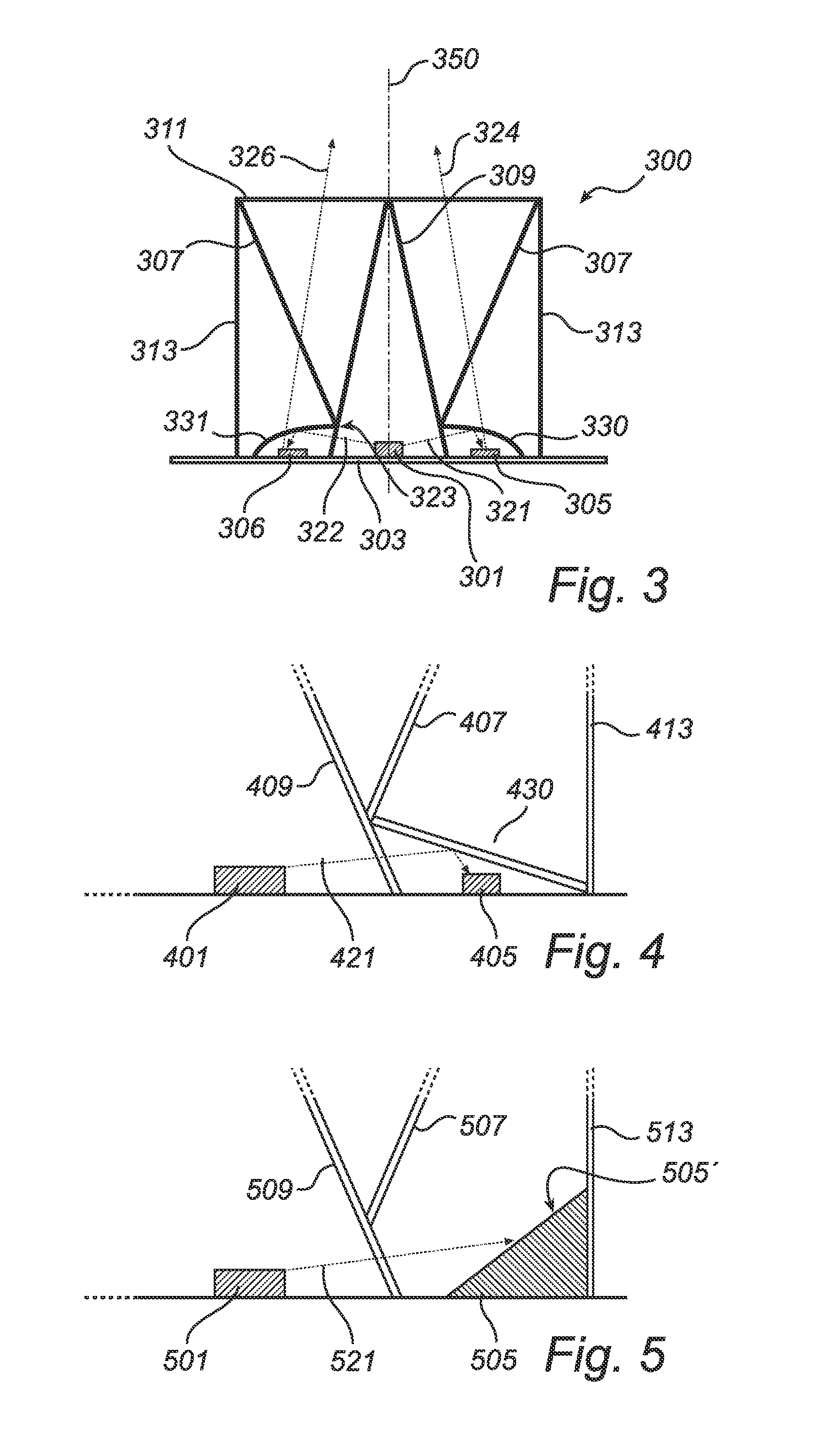
[0037]Hence, now with reference to FIG. 3, a lighting system 300 will be described.
[0038]A light emitting diode 301 (LED), capable of emitting blue light 321, 322 is mounted on a substrate 303, on each side of which is arranged two phosphor structures 305, 306 in the form of “dots”. The two-phosphor dots 305, 306 convert the blue light 321, 322 from the LED 301 into yellow light 324, 326.
[0039]Above the phosphor dots 305, 306 is a first dichroic mirror structure 307 arranged, which is capable of reflecting blue light (not shown in FIG. 3) from the LED 301 and transmit yellow light 324 from the phosphor dots 305, 306.
[0040]Above the blue LED 301 is a second dichroic mirror structure 309 arranged, which is capable of reflecting the light 326 from the phosphor dots 305, 306 and transmit the light 321, 322 from the LED 301, such that no light from the phosphor dots 305, 306 can find it's way back to the LED 301 and thereby be absorbed.
[0041]The blue light 321, 322 is allowed to reach th...
PUM
Abstract
A high efficiency lighting system (100) is described that has a small etendue. This can be used, for example, for backlighting a display device such as a liquid crystal display (LCD), projection displays, as well as for general lighting purposes. A portion of the light from a light emitting device die (101) falls onto a fluorescent material (105,106), such as phosphor. Dichroic mirrors (107,109) prevent the light generated by the fluorescent material to return to the light-emitting device. The mirrors may also provide collimation of the generated light and the remainder of the light from the light-emitting device. In this way a high efficiency system is realized because little or no generated light is absorbed and the generated light does not have to travel through a fluorescent material layer and thus has a high chance to go in the desired direction.
Description
TECHNICAL FIELD[0001]The present invention relates to lighting systems where a light-emitting device is arranged with a fluorescent material and dichromatic surfaces.BACKGROUND[0002]Recently, much progress has been made in increasing the brightness of light emitting device such as light-emitting diodes (LEDs). As a result, it is anticipated that in the years to come, LEDs will become sufficiently bright and inexpensive to serve as a light source in, for example, lamps with adjustable colour, direct view Liquid Crystal Displays (LCDs) and in front and rear projection displays.[0003]Often it is required that a high lumen efficacy is obtained. If LED dies that emit blue light and converting part of the blue light into yellow light are used, a high lumen efficacy may be obtained. Such devices include those where a LED die is covered by a layer of phosphor. However, a drawback with such phosphor covered LED dies is that a lot of the light that is generated exits the phosphor layer in a w...
Claims
Application Information
Patent Timeline
Application Date:The date an application was filed.
Publication Date:The date a patent or application was officially published.
First Publication Date:The earliest publication date of a patent with the same application number.
Issue Date:Publication date of the patent grant document.
PCT Entry Date:The Entry date of PCT National Phase.
Estimated Expiry Date:The statutory expiry date of a patent right according to the Patent Law, and it is the longest term of protection that the patent right can achieve without the termination of the patent right due to other reasons(Term extension factor has been taken into account ).
Invalid Date:Actual expiry date is based on effective date or publication date of legal transaction data of invalid patent.
