
Apparatus and method for activating system of vehicle

a technology of vehicle and apparatus, applied in the direction of propulsion using engine-driven generators, electric devices, process and machine control, etc., can solve the problem of not resuming charging, and achieve the effect of reliable activation

Inactive Publication Date: 2010-11-25
TOYOTA JIDOSHA KK
View PDF2 Cites 37 Cited by
  • Summary
  • Abstract
  • Description
  • Claims
  • Application Information

AI Technical Summary

Benefits of technology

[0027]In the present invention, the system of the vehicle is activated in accordance with the system activation operation by the user when travel of the vehicle is requested, and the system is activated in accordance with any one of the connection signal (connector signal CNCT) and the pilot signal (pilot signal CPLT) when charging of the power storage device from the power supply external to the vehicle is requested. Therefore, the system is activated in accordance with the pilot signal even when the connection signal is abnormal or is not generated. Here, the pilot signal is a signal whose pulse width is modulated based on the magnitude of the rated current that can be supplied to the vehicle through the charging cable. Since the pilot signal is provided in the non-pulsed manner until the system is activated, the pilot signal can be recognized even if the pilot signal has a long sampling cycle.
[0028]Thus, according to the present invention, the vehicle system can be reliably activated when the power storage device is charged from the power supply external to the vehicle. In addition, since the system can be activated in accordance with any one of the connection signal and the pilot signal, the system can be activated in accordance with the pilot signal even when the connection signal is not generated after recovery from a power failure. Furthermore, the system can be activated even when the connection signal is abnormal, and the activation of the system enables the abnormality in the connection signal to be detected.

Problems solved by technology

In the vehicle system where a power supply is activated in accordance with the operation of a limit switch when a paddle of a charging cable is inserted into a charging port of a vehicle, there is a problem that, when a power failure occurs during charging, the vehicle system stops and the paddle remains inserted into the charging port, and thereby, charging is not resumed even when the infrastructure side recovers from the power failure.

Method used


Image

  • Apparatus and method for activating system of vehicle
  • Apparatus and method for activating system of vehicle
  • Apparatus and method for activating system of vehicle

Examples


Embodiment Construction

[0044]Embodiments of the present invention will be hereinafter described in detail with reference to the drawings. The same or corresponding portions are represented by the same reference characters in the drawings, and description thereof will not be repeated.

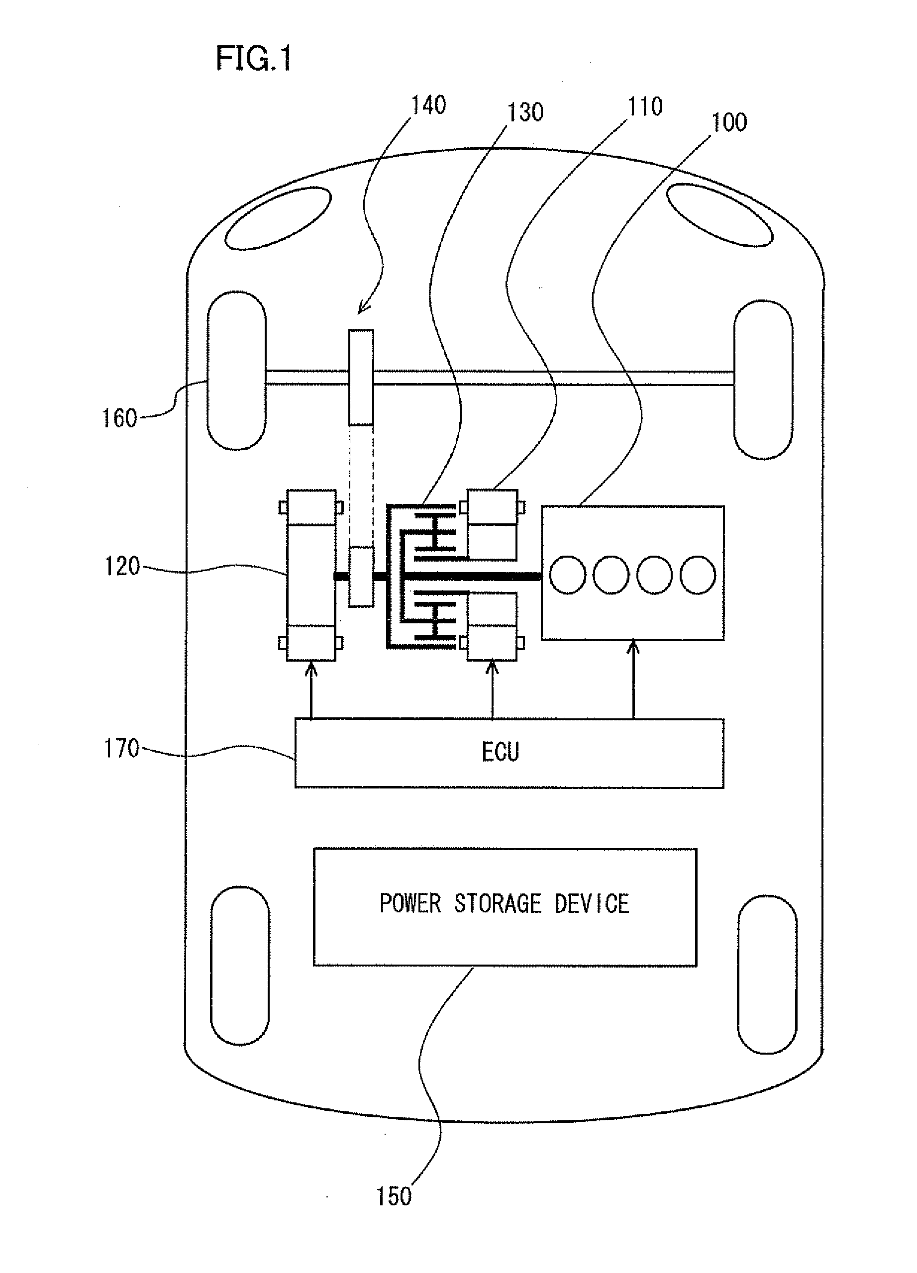
[0045]FIG. 1 is an overall block diagram of a plug-in hybrid vehicle shown as an example of a vehicle to which a system activation apparatus according to an embodiment of the present invention is applied. Referring to FIG. 1, this plug-in hybrid vehicle includes an engine 100, a first MG (Motor Generator) 110, a second MG 120, a power split device 130, a reduction gear 140, a power storage device 150, a drive wheel 160, and an ECU 170.

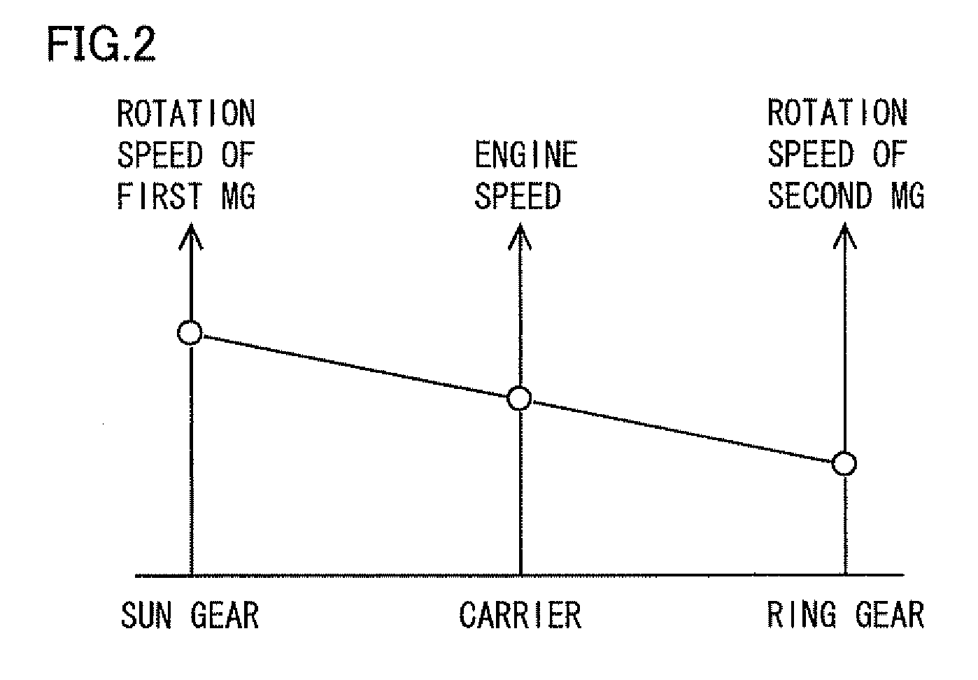
[0046]Engine 100, first MG 110 and second MG 120 are coupled to power split device 130. This plug-in hybrid vehicle travels by using driving force from at least one of engine 100 and second MG 120. Motive power generated by engine 100 is split by power split device 130 into two paths, that is, on...


PUM


Abstract

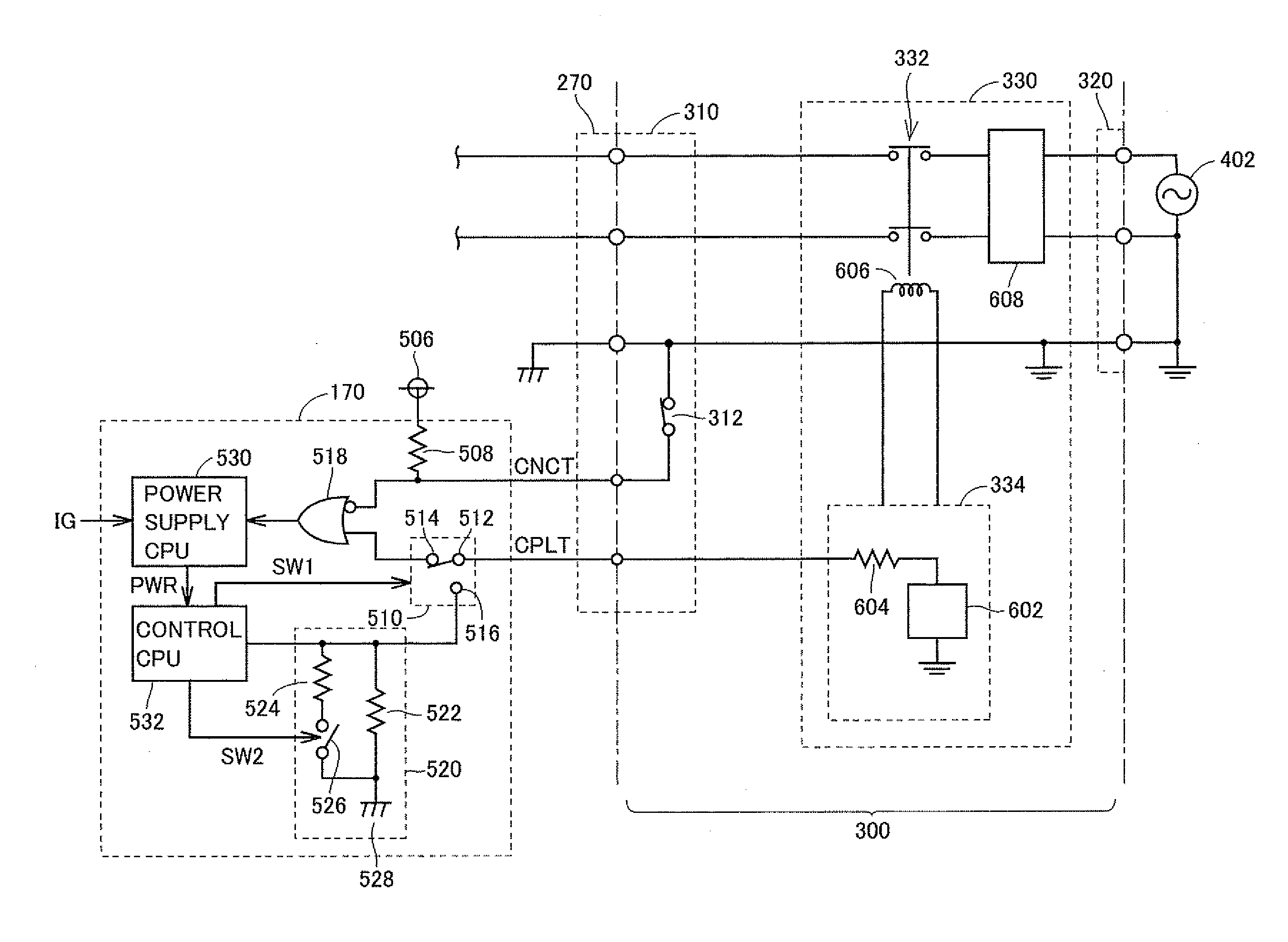
Until a vehicle system is activated, a switching circuit outputs a pilot signal to an OR circuit. As a result, lowering of the potential of the pilot signal caused by a resistance circuit is avoided, and the pilot signal is provided in a non-pulsed manner. A power supply CPU is activated in accordance with any one of a connector signal and the non-pulsed pilot signal. When the vehicle system is activated, the switching circuit switches an output destination of the pilot signal to the resistance circuit.

Description

TECHNICAL FIELD[0001]The present invention relates to an apparatus and a method for activating a system of a vehicle. In particular, the present invention relates to an apparatus and a method for activating a system of a vehicle configured to be capable of charging a vehicle-mounted power storage device for driving the vehicle from a power supply external to the vehicle.BACKGROUND ART[0002]In recent years, an electric vehicle, a hybrid vehicle, a fuel cell vehicle and the like have received attention as an environmentally-friendly vehicle. On these vehicles, a motor that generates driving force for traveling as well as a power storage device that stores electric power supplied to the motor are mounted. The hybrid vehicle further has an internal combustion engine mounted thereon as a power source, together with the motor. The fuel cell vehicle has a fuel cell mounted thereon as a direct current (DC) power supply for driving the vehicle.[0003]Among these vehicles, a vehicle is known i...

Claims


Application Information

Patent Timeline
Patent Type & Authority Applications(United States)
IPC IPC(8): G06F19/00B60L11/18B60K6/445B60L50/15B60L50/16B60W10/26B60W20/00H02J7/00
CPCB60K1/02Y02T90/14B60K6/445B60L3/0023B60L11/123B60L11/14B60L11/1812B60L11/1814B60L11/1816B60L15/007B60L2220/14B60L2220/54B60L2240/80B60W10/06B60W10/26B60W20/00Y02T10/6217Y02T10/6239Y02T10/6269Y02T10/641Y02T10/7005Y02T10/7077Y02T90/127B60K6/365Y02T10/7072B60W2710/248B60L53/14B60L53/22B60L50/61B60L50/16B60L53/24Y02T10/62Y02T10/64Y02T10/70B60W2710/24B60W10/24B60W20/10Y02T90/12
Inventor MITSUTANI, NORITAKE
Owner TOYOTA JIDOSHA KK
Learn More