"improvement in or relating to thickeners having self-diluting feedwell"

a thickener and self-diluting technology, which is applied in the direction of sedimentation settling tanks, liquid displacement, separation processes, etc., can solve the problems of increased construction costs associated with the provision of a larger tank, lack of good control, and simple use of gravity and differential densities, so as to improve the flow pattern of liquid inside the tank, save the cost of flocculent, and reduce the cost of consumables

Active Publication Date: 2010-12-02
TAKRAF
View PDF5 Cites 7 Cited by
  • Summary
  • Abstract
  • Description
  • Claims
  • Application Information

AI Technical Summary

Benefits of technology

[0015]The invention enables a substantial saving in the cost of flocculent per ton of solids in the feed stock, to be achieved. Furthermore, the use of the second launder enables an improved flow pattern of liquid inside the tank to be obtained. Finally a reduction in the cost of consumables is obtainable. These advantages follow from the fact that when supernatant liquid required for diluting the feedstock is drawn directly by a receiving vessel from the interior of the tank in the vicinity of the feed well, an upward flow of the supernatant liquid occurs inside the tank. Localized disturbance of the bed of flocculated material results from this upward flow, and flocculated material is then entrained in the supernatant liquid flowing towards the overflow launder. The risk of disturbance of the bed of flocculated material is much reduced when the supernatant liquid for diluting the feedstock is obtained from the second launder rather than from the thickening tank itself.
[0016]These and other objects, features and advantages are accomplished according to the instant invention by providing a thickening tank having a peripheral overflow launder and a centrally disposed feed well. Feedstock slurry is fed through a duct to a mixing box which also receives a controlled flow of supernatant liquid from a side opening. The mixture from the box supplemented by flocculated material flows into the interior of the feed well by way of a pipe and discharges downwardly from the bottom and onto a distributor baffle plate. The supernatant liquid admitted through the side opening is delivered at a controlled rate from a receiving vessel. This is formed by an upright cylinder provided at its lower end with an impeller of a lift pump which is operated at a controlled rate by a controller positioned at the upper end of a vertical drive shaft extending axially through the receiving vessel. The feed well is surrounded by a second launder which is closed at its base and is formed in the base with a cup. The lower end of the receiving vessel is spaced from the floor of the cup so that it draws supernatant liquid exclusively from the second launder rather than from the interior of the thickener tank. Undesirable changing current flows in the tank are thus avoided when the rate of delivery of supernatant liquid to the mixing box is changed by the controller.

Problems solved by technology

The use of gravity and differential densities, although simple, lacks good control.
The technique involving the pumping of dilution liquid collected in the peripheral overflow launder surrounding the tank, involves additional expense.
This results from the increased constructional costs associated with the provision of a larger tank together with additional pipe work extending between the launder and the feed well.
Finally the technique of submerging or partly-submerging pumping apparatus inside the thickening tank in one or more positions can disrupt the smooth flow of liquid through the tank and traveling radially outwards towards the overflow launder.
This follows from the risk of occurrence of changing, highly localized, rising flow rates occurring inside regions of the tank.
These can adversely affect the clarity of the supernatant liquid entering the overflow launder with consequential operational problems caused by the changing liquid flow patterns inside the tank with different levels of operation of the pumping apparatus.
Such disruption can result in a thick and even layer of flocculated material residing in the hindered settling zone being partially broken up and, as a consequence, some of the flocculated material being carried with the supernatant liquid into the overflow launder to adversely affect its clarity as well as the efficient working of the thickening tank through regions of depletion of the flocculated layer in the hindered settling zone.

Method used


Image

  • "improvement in or relating to thickeners having self-diluting feedwell"
  • "improvement in or relating to thickeners having self-diluting feedwell"
  • "improvement in or relating to thickeners having self-diluting feedwell"

Examples


Embodiment Construction

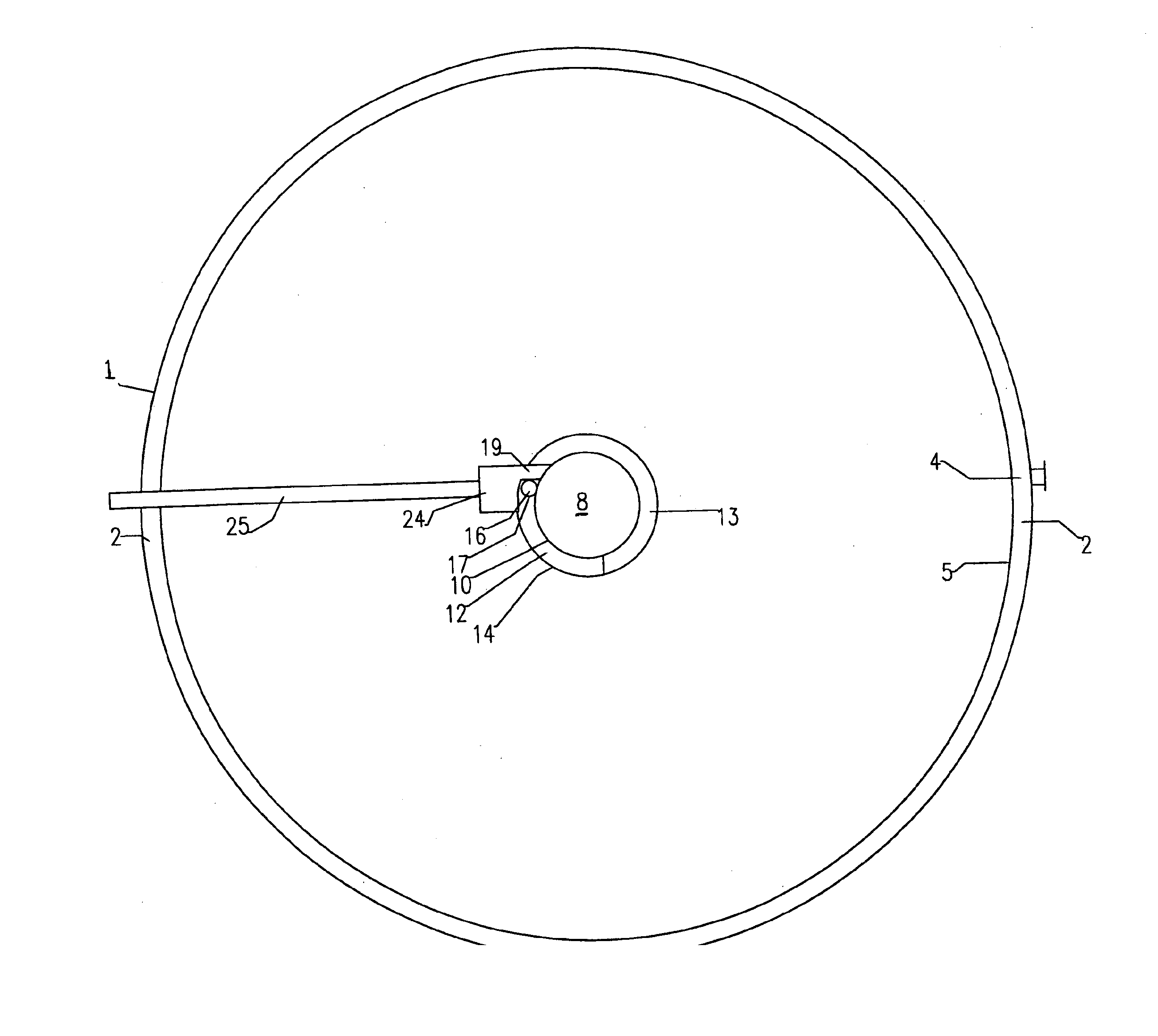
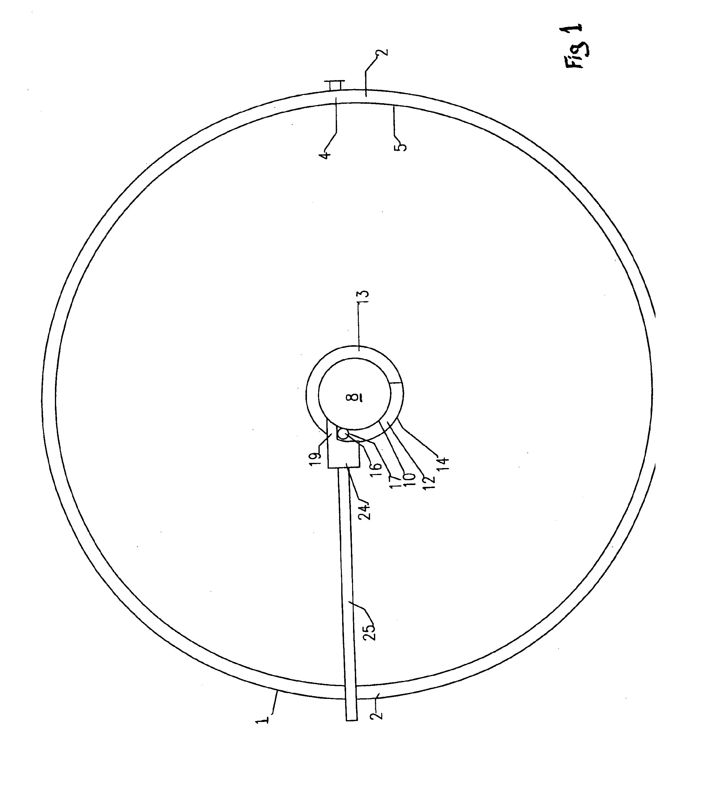
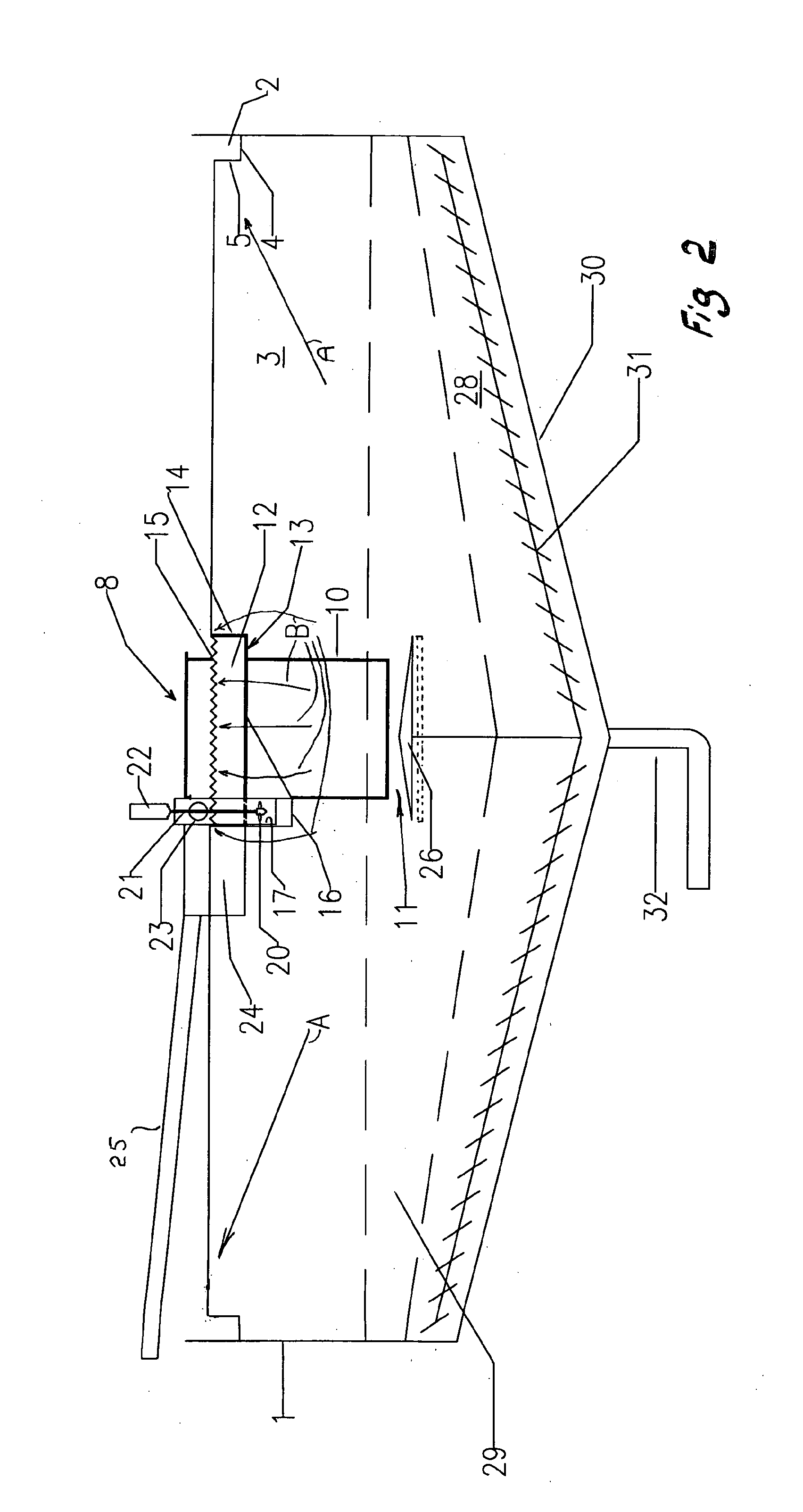
[0020]FIG. 1 shows an upright cylindrical thickening tank 1 having a peripheral overflow launder 2 extending around the inside of an upper portion 3 of the tank. The launder is closed at its base 4 and it has an inner cylindrical wall 5. Supernatant liquid from the upper portion 3 of the tank 1 flows symmetrically in a radially outwards direction into the launder 2.

[0021]A feed well shown generally at 8 is mounted in the central region of the upper portion 3 of the thickener tank 1 and comprises a cylindrical casing 10 open at its underside 11 and surrounded by a second launder 12 arranged slightly beneath the level of the overflow launder 2. The second launder has its base 13 closed and its external wall 14 is formed with a V-notch weir 15 or horizontal wet edge which allows supernatant liquid to enter the launder. The second launder may be formed with circumferentially-spaced parts (not shown) which are individually vertically adjustable in a controlled manner to ensure a smooth a...


PUM

PropertyMeasurementUnit
shapeaaaaaaaaaa
sizeaaaaaaaaaa
flocculationaaaaaaaaaa

Abstract

A thickening tank has a peripheral overflow launder and a centrally disposed feed well. Feedstock slurry is fed to a mixing box which also receives supernatant liquid and is supplemented by flocculated material flowing into the interior of the feed well onto a distributor baffle plate. The supernatant liquid is delivered at a controlled rate from a receiving vessel formed by an upright cylinder provided at its lower end with an impeller of a lift pump which is operated by a controller positioned at the upper end of a vertical drive shaft extending axially through the receiving vessel. The feed well is surrounded by a second launder which is closed at its base and formed with a cup. The lower end of the receiving vessel is spaced from the floor of the cup to draw supernatant liquid exclusively from the second launder rather than from the thickener tank.

Description

CROSS-REFERENCE TO RELATED APPLICATIONS[0001]This application claims priority on PCT Patent Application No. PCT / AU2008 / 001782, filed Dec. 2, 2008, in which the United States of America was a Designated State.FIELD OF THE INVENTION[0002]This invention relates to a method and apparatus for the dilution of a thickener feed to a thickener tank and is concerned, although not exclusively so, with industries in which liquid is separated from solids in suspended pulps. One such industry occurs in the field of mineral extraction and mineral processing. Another such industry occurs in the operation of clarifiers used in the treatment of sewage. For convenience the invention will hereinafter be described with reference to the extraction of mineral ore from a feedstock slurry but it is to be understood that the invention is also applicable to other industries where thickening of a feedstock is required.BACKGROUND OF THE INVENTION[0003]A typical thickener takes the form of an upright cylindrical...

Claims


Application Information

Patent Timeline
Patent Type & Authority Applications(United States)
IPC IPC(8): F17D3/00B65D90/02
CPCB01D21/0042B01D21/01B01D21/06B01D21/2405C02F2001/007B01D21/30B01D21/34B01D2221/04B01D21/2427Y10T137/0318B01D21/24C02F1/52
Inventor MCELVENNY, RHETT
Owner TAKRAF
Why Eureka
Try Eureka