Interferometric fiber optic gyroscope with silicon optical bench front-end

a fiber optic gyroscope and silicon optical technology, applied in the field of interferometric fiber optic gyroscope with silicon optical bench front-end, can solve the problem that the siob technology has not been exploited, and achieve the effects of reducing the cost of the ifog, increasing reliability, and reducing cos

Active Publication Date: 2010-12-02
HONEYWELL INT INC
View PDF9 Cites 14 Cited by
  • Summary
  • Abstract
  • Description
  • Claims
  • Application Information

AI Technical Summary

Benefits of technology

[0006]The present invention integrates IFOG passive optical and active electro-optical functions onto a single silicon substrate. Because the silicon substrate employs self-aligning features, the silicon substrate optical system can be manufactured with automation

Problems solved by technology

Fusion splicing and stowage processes add many manual process steps to IFOG manufacturing, thus having a significant contribution to IFOG cost along with that of the discrete optical components.
Howeve

Method used


Image

  • Interferometric fiber optic gyroscope with silicon optical bench front-end
  • Interferometric fiber optic gyroscope with silicon optical bench front-end
  • Interferometric fiber optic gyroscope with silicon optical bench front-end

Examples


Embodiment Construction

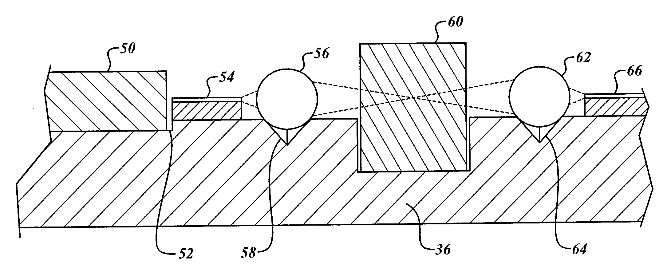
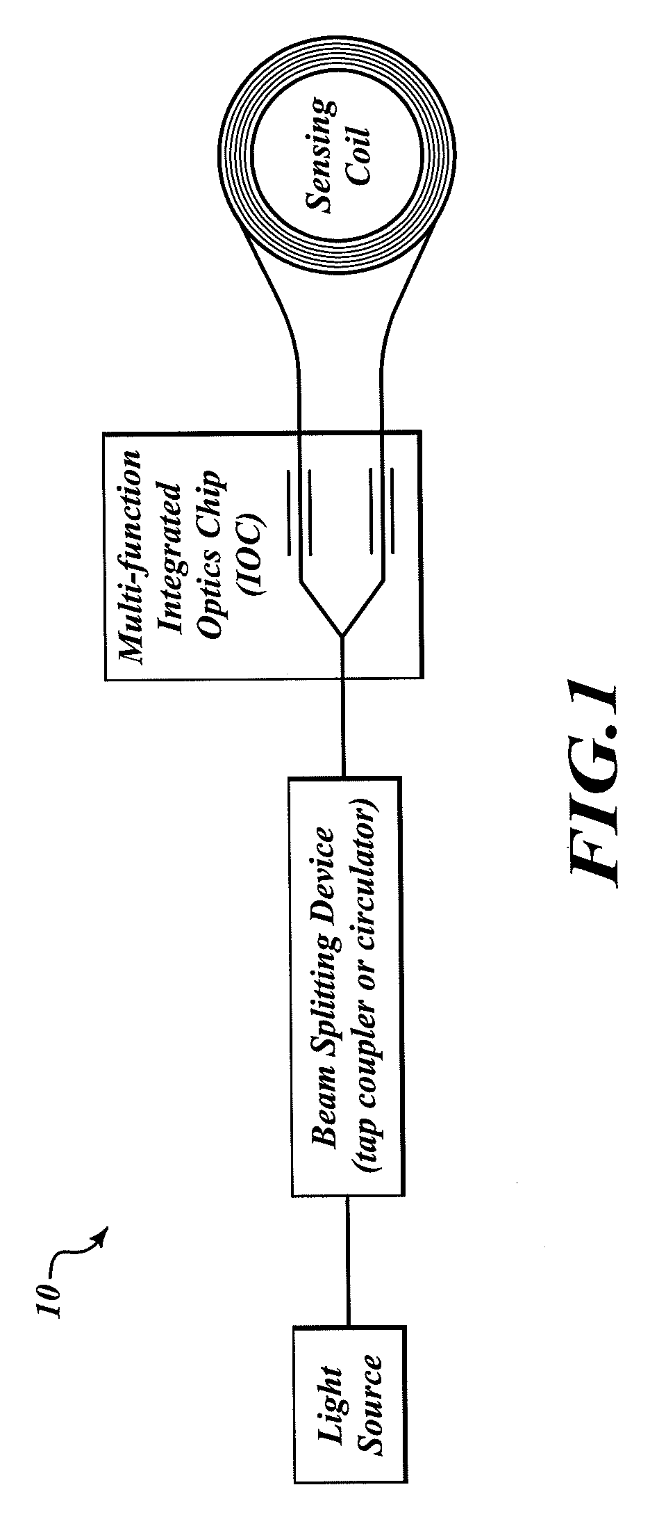
[0016]The present invention integrates passive optical and active electro-optical functions of an interferometric fiber optic gyroscope (IFOG), onto a single silicon substrate. An example of an IFOG is shown in FIG. 1. Optical front-end components, also known as commercial off-the-shelf (COTS) optical components, can be purchased in unpackaged form and assembled onto the single silicon substrate, decreasing the size and cost of the IFOG while increasing the reliability. In an exemplary embodiment, the invention includes a silicon substrate optical system consisting of a silicon substrate on which COTS optical components are assembled. The silicon substrate optical system is referenced in FIG. 2 below.

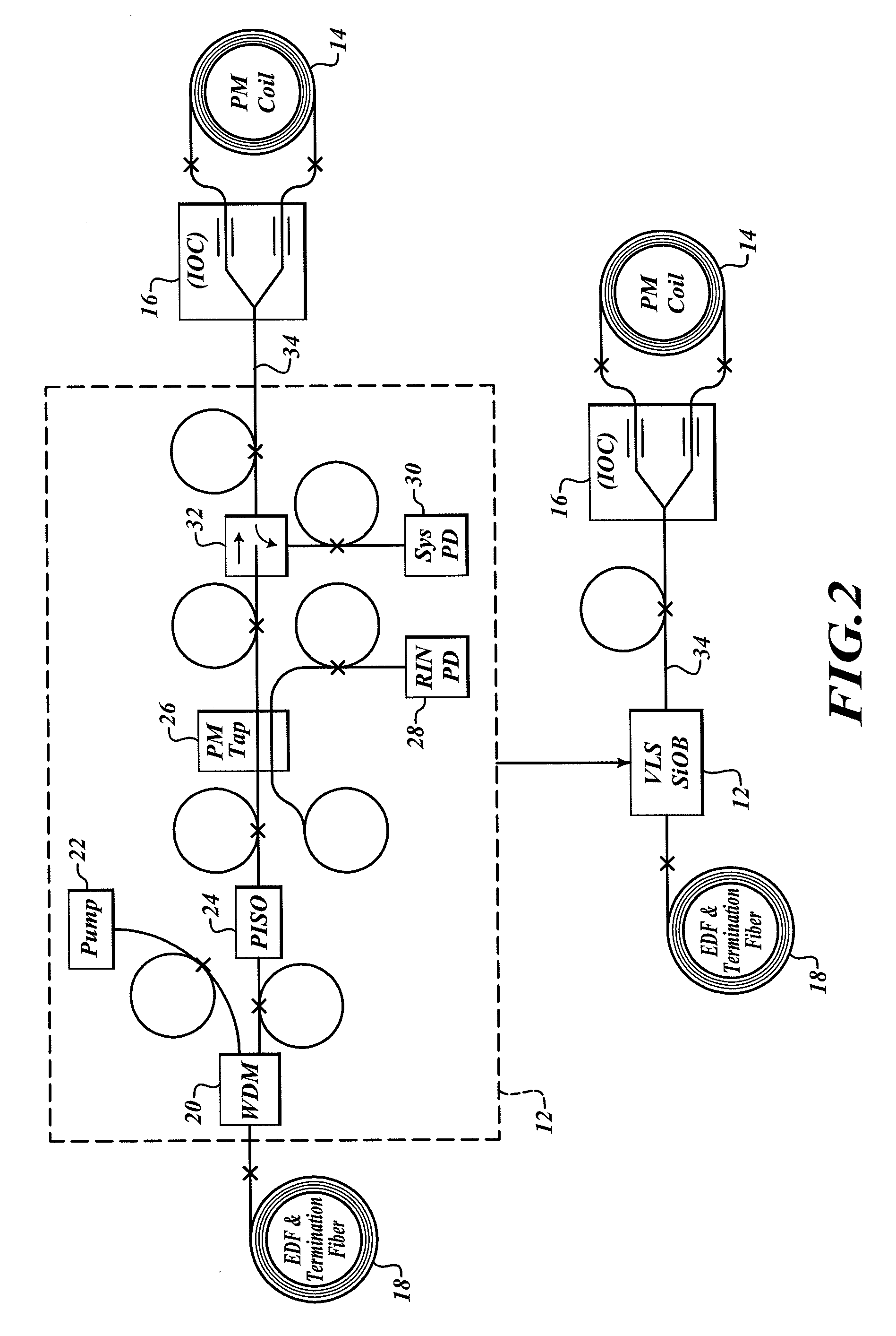
[0017]FIG. 2 is a partial schematic diagram of an IFOG in accordance with the present invention. In general, a silicon substrate optical system 12 comprises a plurality of COTS optical components. In the exemplary embodiment of FIG. 2, the COTS optical components include a wavelength di...


PUM


Abstract

Method and apparatus are provided for a silicon substrate optical system for use in an interferometric fiber optic gyroscope (IFOG). A silicon substrate of the silicon substrate optical system is etched to receive optical components, including an input optical fiber, a pump source, a wavelength division multiplier, an isolator, a polarizing isolator, a beam splitting device, a PM tap coupler, a relative intensity noise (RIN) photodiode, a system photodiode, and an output optical fiber. The optical components are mounted on a silicon substrate to reduce the size and cost of the IFOG and increase reliability.

Description

BACKGROUND OF THE INVENTION[0001]Gyroscopes have been used to measure rotation rates or changes in angular velocity about an axis of rotation. A basic conventional fiber optic gyroscope (FOG) includes a light source, a beam generating device, and a fiber optic coil coupled to the beam generating device that encircles an area. Rotation about the axis normal to the fiber optic coil either slows or speeds the propagation of the light through the coil, resulting in a measureable shift in phase of the light.[0002]In an interferometric fiber optic gyroscope (IFOG), the light source is split into two beams that propagate in opposite directions through the fiber optic coil. After propagating through the coil, the two beams of light are recombined to compare the phase upon exit from the coil. Recombining the beam produces an interference pattern indicative of the phase of the respective beams. At a detector, shifts in the interference pattern are proportional to the phase difference between ...

Claims


Application Information

Patent Timeline
IPC IPC(8): H01L33/00H01L21/50G01C19/72
CPCG01C19/722G01C25/00G02B6/43G02B6/423G02B6/4236G02B6/3608
Inventor STRANDJORD, LEESTRABLEY, JENNIDETRY, JAMES F.
Owner HONEYWELL INT INC
Why Eureka
Try Eureka