Projection-type image displaying apparatus

a technology of projection-type images and displaying apparatuses, which is applied in the direction of projectors, optics, instruments, etc., can solve the problems of cost-up, inability to reproduce the original image faithfully, and degrade the color balance of the screen, so as to reduce the color change of the image, avoid the increase of a number of components and cost-up, and improve the brightness of the image

Inactive Publication Date: 2010-12-02
RICOH KK
View PDF8 Cites 38 Cited by
  • Summary
  • Abstract
  • Description
  • Claims
  • Application Information

AI Technical Summary

Benefits of technology

[0026]An object of the present invention is to provide an image displaying apparatus in which an APC is performed to suppress color change of an image due to change in a light source output, the APC being performed in an image forming area to allow an area which is

Problems solved by technology

Thereby, color balance on the screen S is degraded so that a faithful color reproduction of the original image cannot be achieved.
This becomes a factor for cost-up.
In addition, a wavelength of the light source such as a semiconductor laser varies due to temperature and therefore if a light flux splitting optical system formed of

Method used


Image

  • Projection-type image displaying apparatus
  • Projection-type image displaying apparatus
  • Projection-type image displaying apparatus

Examples


embodiment 1

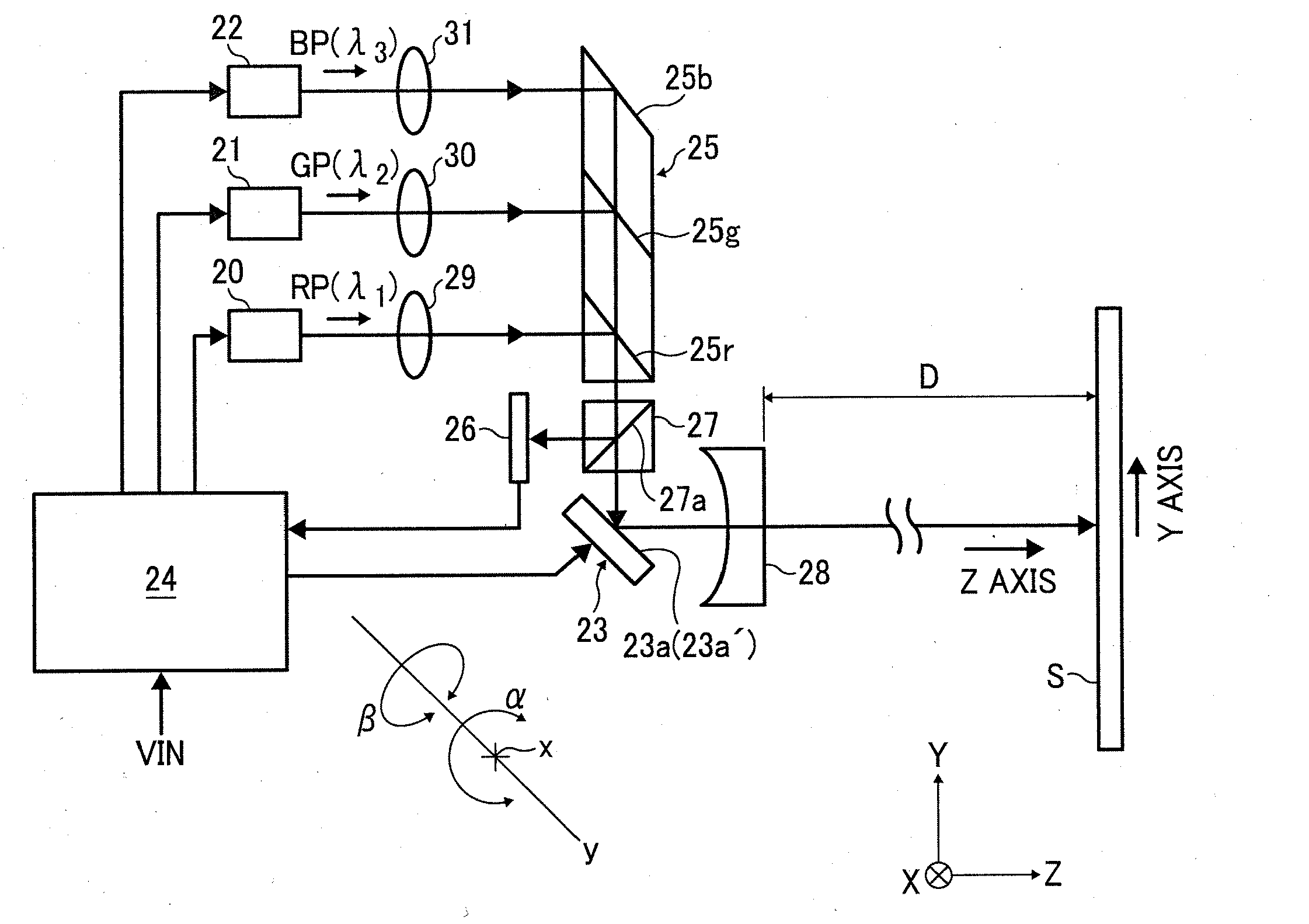
[0050]FIG. 1 is a view showing an optical system of a projection-type image display apparatus according to an embodiment of the present invention.

[0051]In FIG. 1, reference number 20 indicates a laser light source configured to emit a red laser light RP (wavelength λ1) as a diverging light, 21 indicates a laser light source configured to emit a green laser light GP (wavelength λ2) as a diverging light, 22 indicates a laser light source configured to emit a blue laser light BP (wavelength λ3) as a diverging light, 23 indicates a MEMS mirror device, 24 indicates a control circuit, 25 indicates a light-path combining prism, 26 indicates a light receiving element for monitoring a light amount (referred to as “light receiving element” or “monitoring light receiving element”), 27 indicates a light-path splitting prism, and 28 indicates a concave lens as a projection lens.

[0052]Original image data (R, G, B data of input video signals, projection position data, and the like) VIN are input t...

example 2

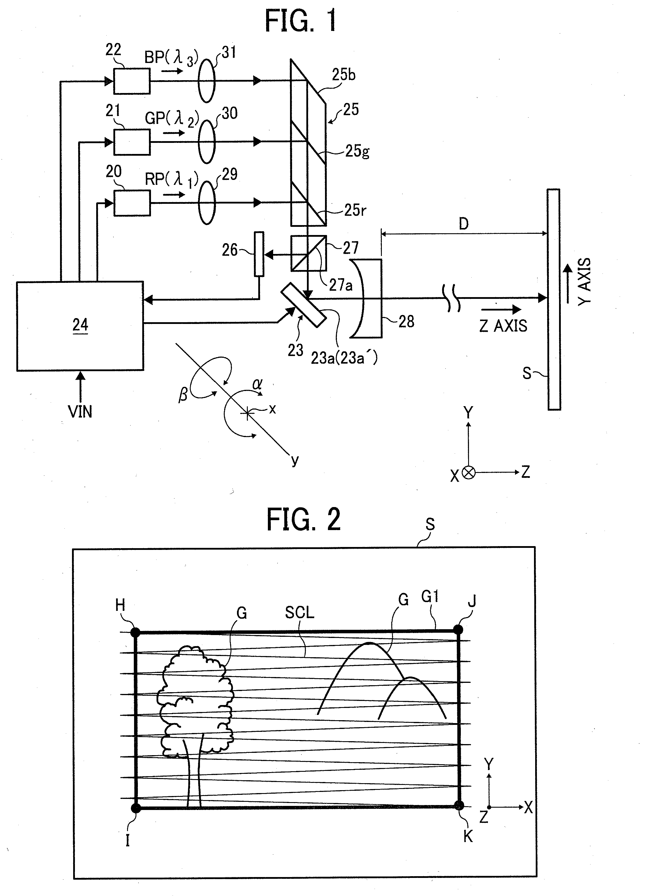
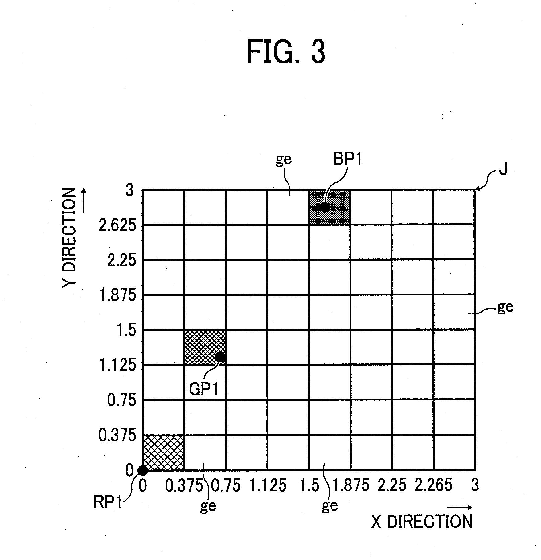
[0103]FIG. 6 is an explanatory view showing a relationship between light emitting timings of the laser light sources 20, 21 and 22 at vicinities of the coordinate points H, I, J and K of the image forming area G1 and emitting light intensities. In FIG. 6, a horizontal axis indicates time t and a vertical axis indicates an emitting light intensity POW. At the vicinities of the coordinate points H, I, J and K, as described above, if the laser light sources 20, 21 and 22 emit the laser lights at a same timing, beam spots of the laser lights RP, GP and BP are respectively formed at different pixels ge from each other on the screen.

[0104]The light emitting timings of the laser light sources 20, 21 and 22 are shifted from each other such that the beam spots of the laser lights RP, GP and BP are formed on the same pixel ge to reproduce a color of the original image data at the pixel.

[0105]It is only needed to determine the emitting light intensity POW as to closely reproduce the color of t...

example 3

[0110]FIG. 7 shows a photoelectric conversion efficiency of the light receiving element 26 in relation to a wavelength. The photoelectric conversion efficiency is shown by a curve which functionally changes, as shown in FIG. 7, in relation to the wavelength. The photoelectric conversion efficiencies are, 0.45, 0.33, and 0.23 (A / W) with respect to the red light RP of the wavelength λ1=640 (nm), the green light (GP) of the wavelength λ2=530 (nm) and the blue light (BP) of the wavelength λ3=445 (nm), respectively.

[0111]Accordingly, if it is supposed that the light receiving element 26 receives same light amounts of the lights of the wavelengths λ1, λ2 and λ3 each other, output currents of the light receiving element 26 are in a proportion of red:green:blue=4:3:2. That is, when the light receiving element receives the red light, the received current which is twice the blue light is output.

[0112]In the second embodiment, at the light emitting timings t1, t2 and t3, the maximum emitting l...


PUM


Abstract

A projection-type image display apparatus for displaying an image on a projected plane, includes light sources each configured to emit a light, a light-path combining element configured to combine light paths of the lights each emitted from the light sources, a light path splitting element configured to split the lights on the combined light path into first and second lights, a scanning mirror configured to reflect the first lights to scan the projected plane with the first lights, a light receiving element configured to receive the second lights to detect light amounts of the received second lights, and a control circuit configured to control the scanning mirror to scan an image forming area of the projected plane with the first lights based on image data and control the light sources so as to reproduce a color based on the image data. The control circuit is configured to control the light receiving element to detect the light amounts of the light sources when the image forming area is scanned with the first light, and adjust emitting light amounts of the light sources based on the detected light amounts of the light sources.

Description

CROSS REFERENCE TO RELATED APPLICATIONS[0001]The present application is based on and claims priority from Japanese Application Numbers 2009-129736, filed on May 29, 2009 and 2010.69060, filed on Mar. 25, 2010, the disclosure of which is hereby incorporated by reference herein in its entirety.BACKGROUND OF THE INVENTION[0002]1. Field of the Invention[0003]The present invention relates to a projection-type image displaying apparatus configured to form an image with scanning lights modulated by and emitted from a plurality of laser light sources.[0004]2. Description of the Related Art[0005]Recently, in order to achieve small size and easily portable apparatus, a projection-type image displaying apparatus (also, referred to as a projector) configured to form an image with scanning lights modulated by and emitted from a plurality of laser light sources or LED light sources has been developed.[0006]Particularly, a scanning-type small size projector configured by combining three primary co...

Claims


Application Information

Patent Timeline
IPC IPC(8): G03B21/14
CPCG03B21/2066G03B33/12
Inventor TAKAHASHI, YOSHITAKAAKIYAMA, HIROSHI
Owner RICOH KK
Why Eureka
Try Eureka