Eureka AIR delivers breakthrough ideas for toughest innovation challenges, trusted by R&D personnel around the world.

High voltage recessed connector contact

a connector and high-voltage technology, applied in the direction of electrical apparatus construction details, coupling device connections, coatings, etc., can solve the problems of high cost, high assembly cost of high-voltage circuit boards, and inconvenient use, so as to reduce the required size, prevent internal arcing, and compact device size

Inactive Publication Date: 2010-12-02
LHV POWER
View PDF4 Cites 10 Cited by
  • Summary
  • Abstract
  • Description
  • Claims
  • Application Information

AI Technical Summary

Benefits of technology

[0019]Another advantage is to use a low-pressure injection molding technique to accelerate the manufacturing process.
[0033]An alternate embodiment of encapsulating high voltage circuitry incorporating a connector contact means will have the metal saddle, conductive rubber slug contact and the integrated high voltage poke-home connector tunnel located on the opposite side of the circuit board. This design will shorten the overall length of the unit and reduce the amount of injection molding material required.

Problems solved by technology

This traditional method requires many steps and much time to complete, and is thus not well suited for high volume, low cost assembly of high voltage circuit boards.
These connectors tend to be expensive and space consuming.
Often in High Voltage work, surface mount components, suitable for high voltage operation, of a specific size and performance are not available, or if they are, they are dramatically more expensive than the conventional “thru-hole” counterpart.
This patent relates to the field of die and lead frame assembly of integrated circuits and to the encapsulation packaging using transfer-molding techniques which is a much slower process than the low pressure injection molding process and less adaptable to a rapid production.
It does not incorporate the low-pressure injection molding process, the conductive rubber slug or the integrated connection tunnel.

Method used


Image

  • High voltage recessed connector contact
  • High voltage recessed connector contact
  • High voltage recessed connector contact

Examples


Embodiment Construction

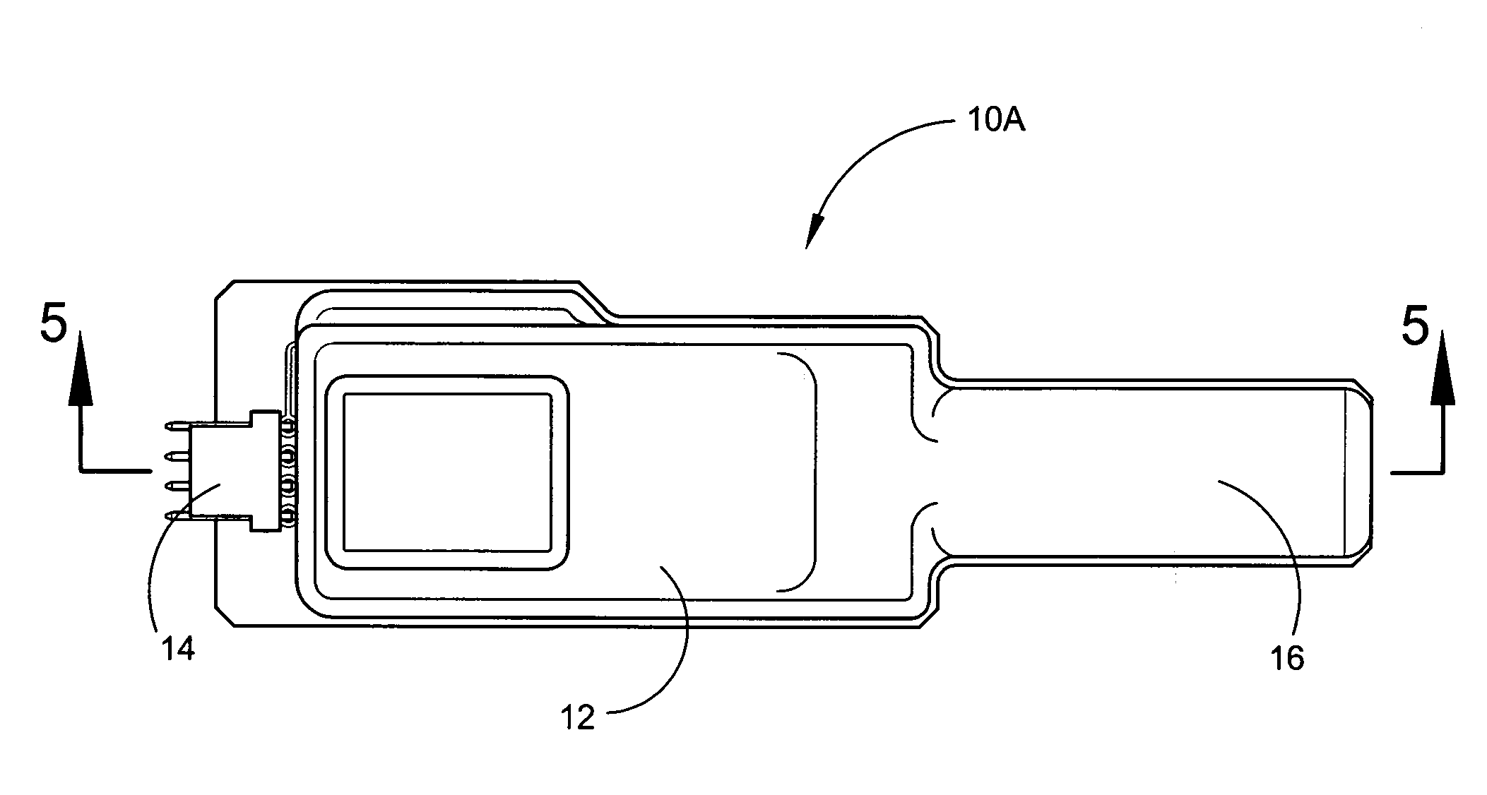
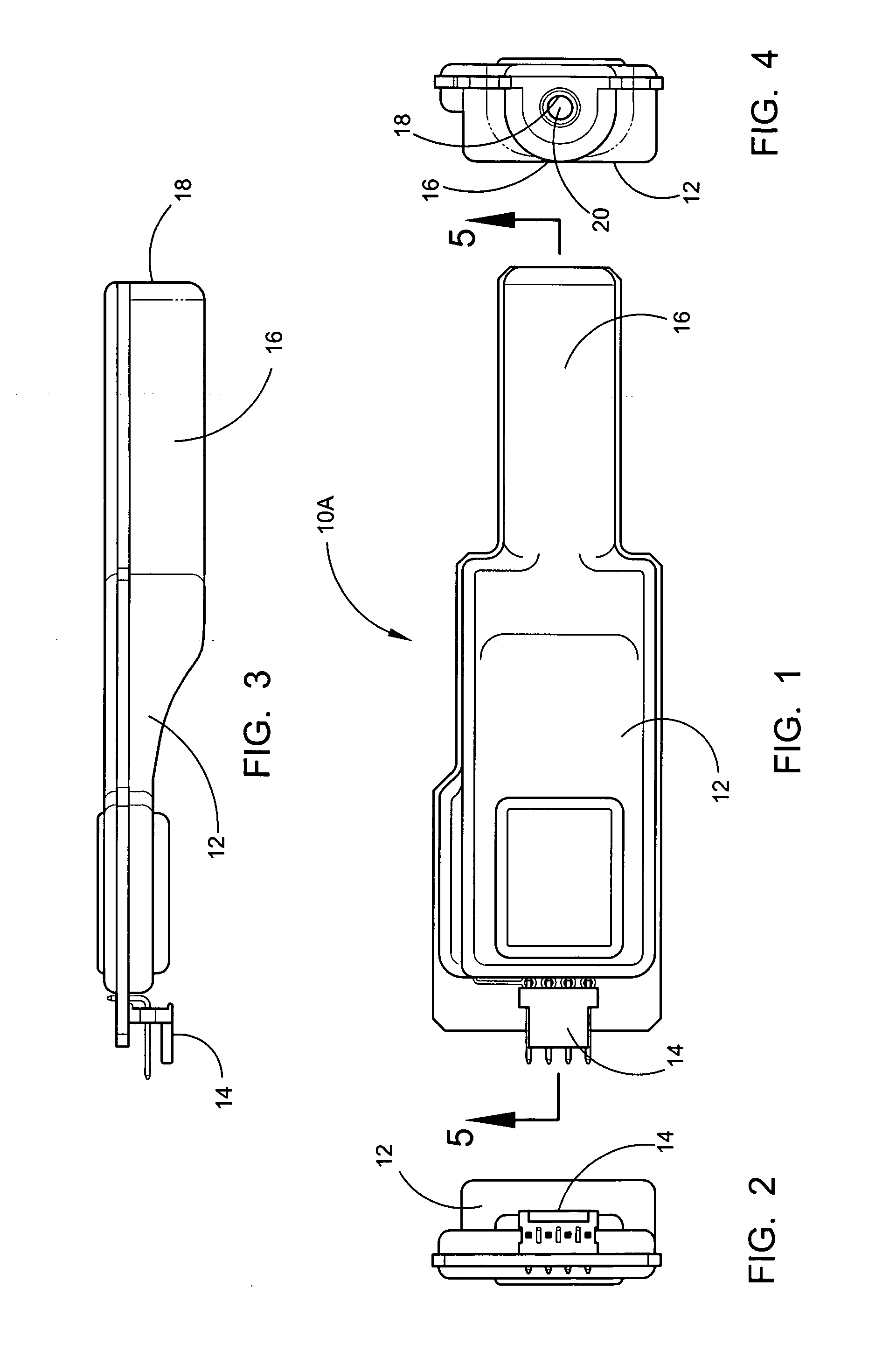
[0047]Referring now to the drawings, wherein similar parts of the process are identified by like reference numerals, there is seen in FIG. 1 a top view of a typical encapsulated high voltage circuit board incorporating the connector contact means 10A where the main body section 12 is shown with the external electrical connector 14 on the left. On the right of the main body section 12 is the extended tunnel end 16 with the tapered poke-home connection tunnel 18.

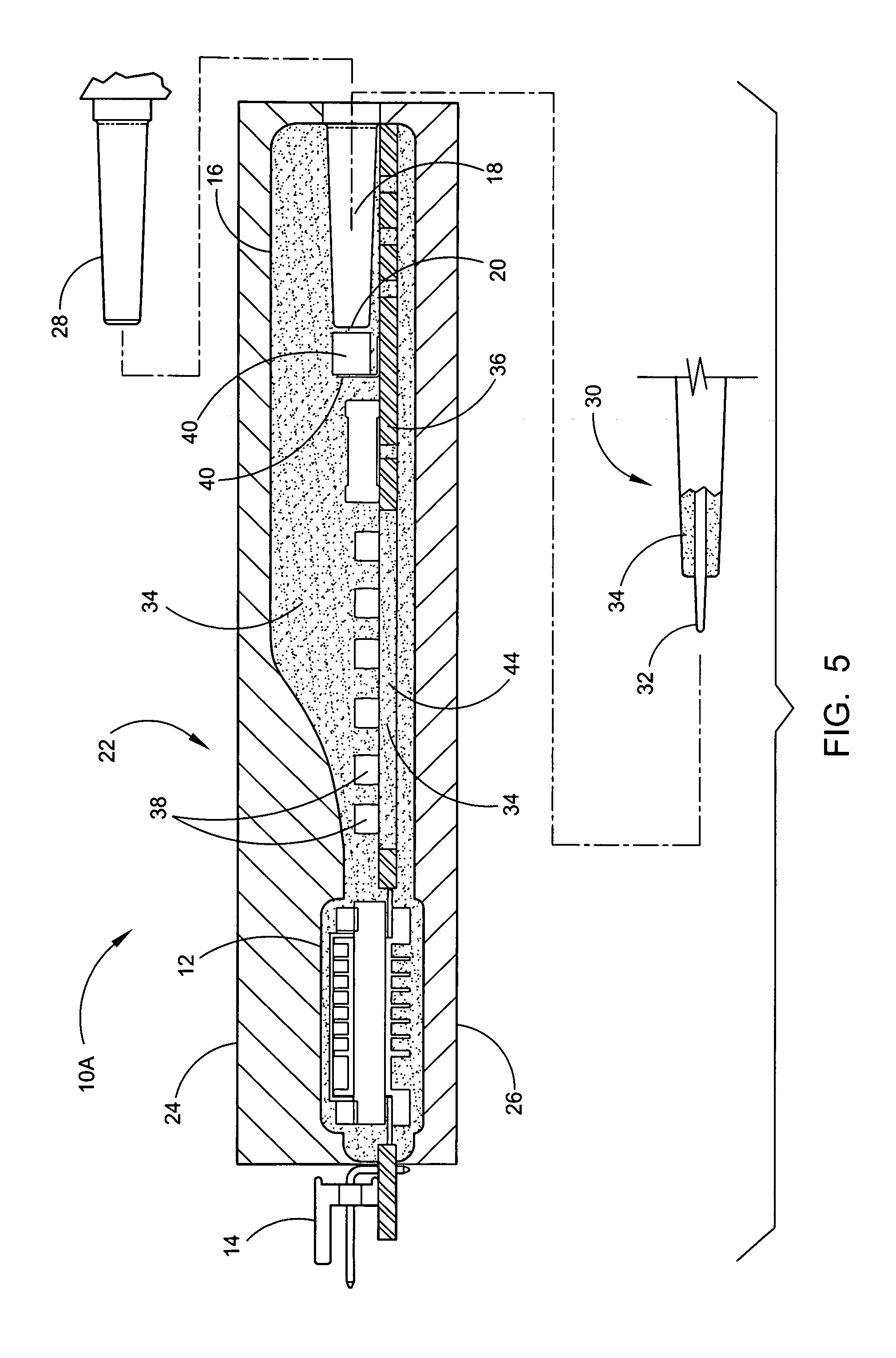
[0048]FIG. 2 depicts an end view of a typical encapsulated high voltage circuit board incorporating the connector contact means 10A illustrating the external electrical connector 14 and the main body section 12. FIG. 3 depicts a side view of a typical encapsulated high voltage circuit board incorporating the connector contact means 10A having the main body section 12 and the extended tunnel end 16. FIG. 4 depicts an end view of a typical encapsulated high voltage circuit board incorporating the connector contact means 10A; ill...


PUM

PropertyMeasurementUnit
voltageaaaaaaaaaa
pressureaaaaaaaaaa
conductiveaaaaaaaaaa

Abstract

A process relating to a one step low pressure injection molding method of encapsulating high voltage circuitry while incorporating a unique recessed high voltage connector contact means within the injection molding material, greatly reducing the component size, while increasing the capabilities of this type of circuitry. The process reduces the manufacturing time and maintains a clean sealed contact point for repeated usage by the means of a conductive rubber slug. An additional advantage is by creating cavities through the circuit board; axially leaded high voltage components may be conveniently mounted without additional assembly components while being fully encapsulated.

Description

[0001]This patent application claims the benefit of U.S. provisional patent application Ser. No. 60 / 899,783 filed on Feb. 6, 2007.FIELD OF THE INVENTION[0002]The process relates to a one step low pressure injection molding method of encapsulating high voltage circuitry while incorporating a unique integrated recessed high voltage connector contact means, greatly reducing the component size, while increasing the capabilities of this type of circuitry and connection means. The process reduces the manufacturing time and maintains a clean sealed contact point for repeated usage. An additional advantage in this process is by creating cavities through the circuit board; axially leaded high voltage components may be conveniently mounted without additional assembly components while being fully encapsulated.BACKGROUND OF THE INVENTION[0003]The standard technique of protecting high voltage circuitry from the environment and from internal arcing, due to the necessity to violate open air constr...

Claims


Application Information

Patent Timeline
Patent Type & Authority Applications(United States)
IPC IPC(8): H05K7/00H01R12/30H05K3/00
CPCH05K2201/09063H05K3/3421B29C45/14639H05K2201/10189H01R24/76H01R2101/00H05K3/284Y10T29/4913H01R13/53H05K1/182Y10T29/49146H05K2201/10651H05K1/0254Y10T29/49124H01R13/5219H05K2203/1316Y10T29/49155
Inventor WING, KENNETH E.CARROLL, SCOTT T.
Owner LHV POWER
Why Eureka
Eureka Blog
Learn More