Achieving low phase noise in external cavity laser implemented using planar lightwave circuit technology

a technology of planar lightwave circuit and external cavity laser, which is applied in the direction of laser details, optical resonator shape and construction, semiconductor lasers, etc., can solve the problems of sensitivity to vibration, prohibitively large size of traditional bulk-optics-based ecls, and inability to meet the requirements of applications, so as to reduce phase noise

Active Publication Date: 2010-12-02
OPTASENSE
View PDF6 Cites 26 Cited by
  • Summary
  • Abstract
  • Description
  • Claims
  • Application Information

AI Technical Summary

Benefits of technology

[0009]According to yet another aspect of the present invention, the operating w

Problems solved by technology

Traditional bulk-optics-based ECLs are prohibitively large in size, and may not be suitable for applications that require a compact device footprint.
Hybrid ECLs based on fi

Method used


Image

  • Achieving low phase noise in external cavity laser implemented using planar lightwave circuit technology
  • Achieving low phase noise in external cavity laser implemented using planar lightwave circuit technology
  • Achieving low phase noise in external cavity laser implemented using planar lightwave circuit technology

Examples


Embodiment Construction

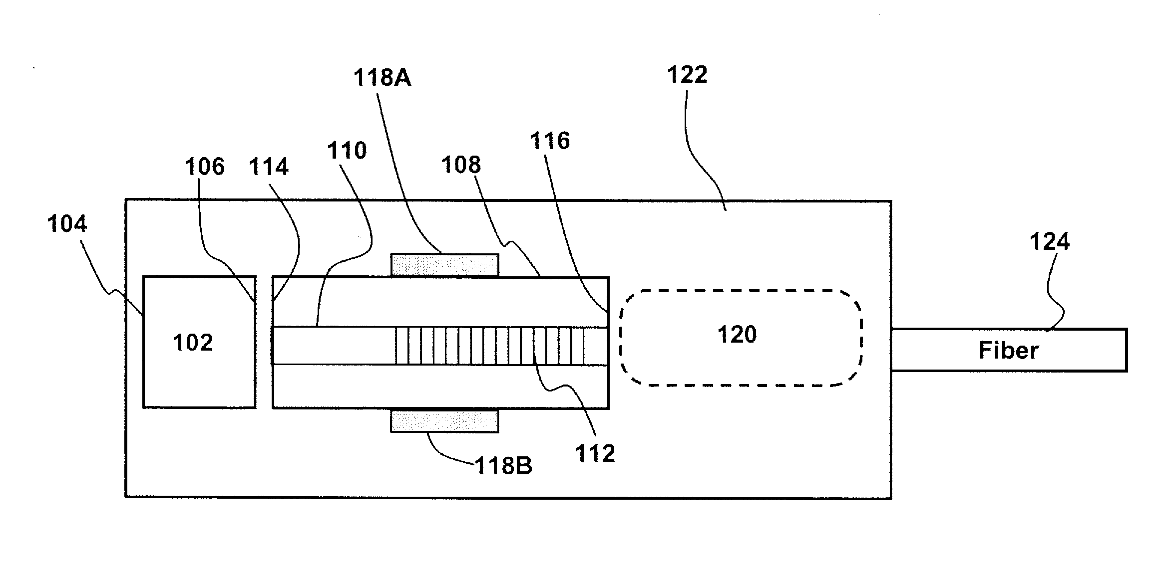
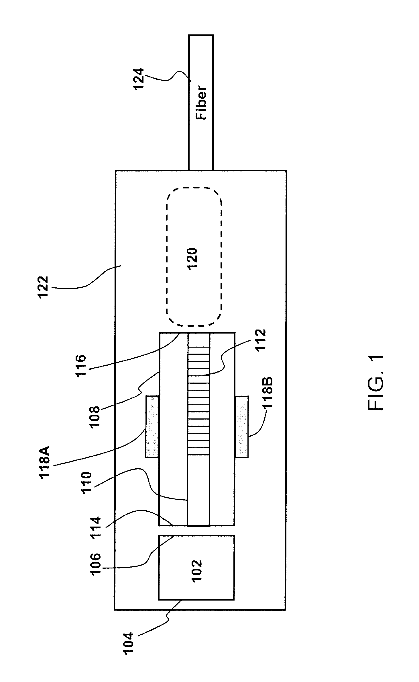
[0020]The present invention will now be described in detail with reference to the drawings, which are provided as illustrative examples of the invention so as to enable those skilled in the art to practice the invention. Notably, the figures and examples below are not meant to limit the scope of the present invention to a single embodiment, but other embodiments are possible by way of interchange of some or all of the described or illustrated elements. Moreover, where certain elements of the present invention can be partially or fully implemented using known components, only those portions of such known components that are necessary for an understanding of the present invention will be described, and detailed descriptions of other portions of such known components will be omitted so as not to obscure the invention. In the present specification, an embodiment showing a singular component should not be considered limiting; rather, the invention is intended to encompass other embodimen...


PUM


Abstract

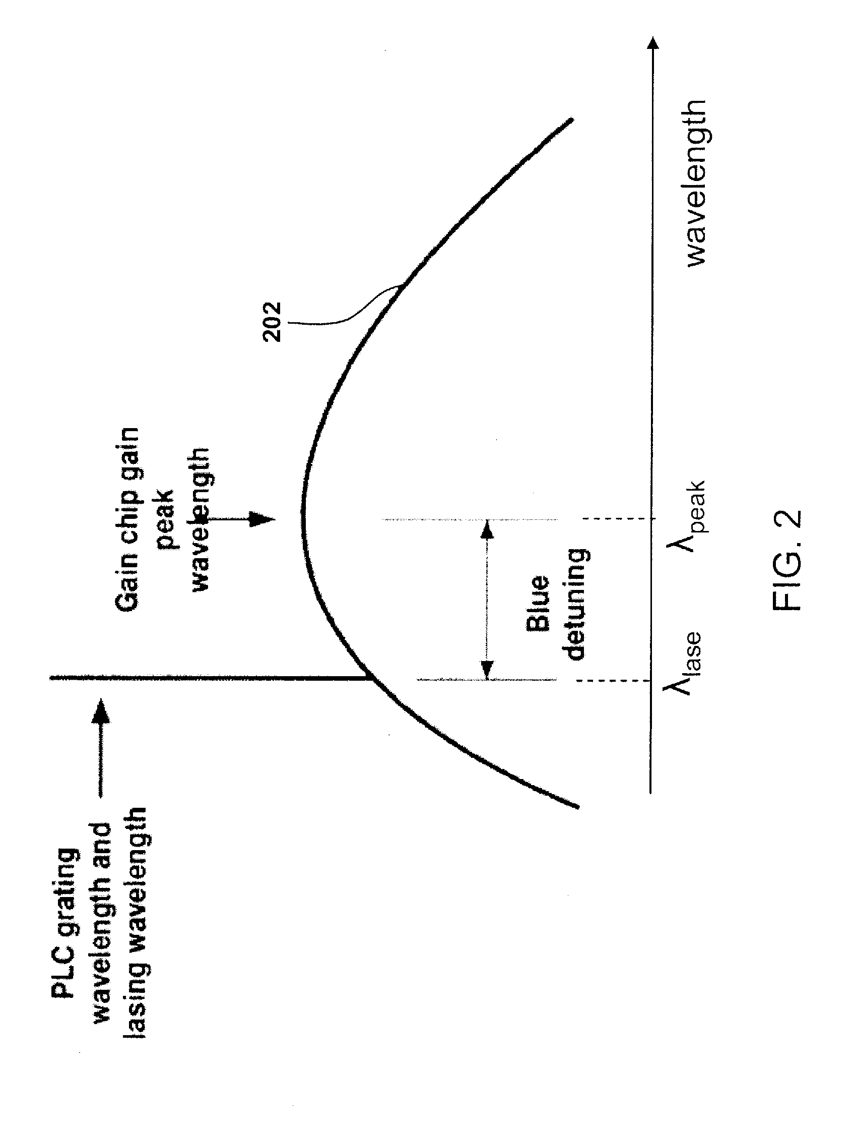
The present invention relates to external cavity laser (ECL) apparatuses and manufacturing processes, and more particularly to implementing low noise narrow bandwidth ECLs on planar lightwave circuit (PLC) platforms for harnessing high-performance, high-stability operation from a compact-footprint, low-power packaged device. An ECL device with narrow linewidth and low noise is disclosed, the device comprising a PLC device and a gain chip butt-coupled to each other. The PLC device has a planar Bragg grating (PBG) integrated onto a rectangular waveguide. The PLC device has anti-reflection coatings (ARC) on its input facet and output facet. The waveguide is designed to be selective of a single polarization. The gain chip has high-reflection coating (HRC) on a back facet and an ARC on a front facet. An operating wavelength of the ECL is aligned to a longer wavelength red slope of a reflectivity spectrum of the PBG. The operating wavelength may be tuned thermally, electrically, or thermo-electrically.

Description

CROSS REFERENCE TO RELATED APPLICATION[0001]This application claims priority from U.S. Provisional Application Ser. No. 61 / 183,183 tiled May 26, 2009.FIELD OF THE INVENTION[0002]The present invention relates to systems and methods of implementing high-performance, high-stability, compact-footprint external cavity lasers.BACKGROUND[0003]External cavity laser (ECL) technology is a robust solution for achieving interferometric sensing and / or other applications, including, but not limited to, distributed structural monitoring, military surveillance, seismic monitoring, telecommunications, data communications, etc. Traditional bulk-optics-based ECLs are prohibitively large in size, and may not be suitable for applications that require a compact device footprint. Semiconductor-based devices offer the advantage of smaller size and lower power consumption. Compared to other existing semiconductor-based interferometric sensing solutions, such as, systems using Distributed Feedback (DFB) lase...

Claims


Application Information

Patent Timeline
IPC IPC(8): H01S3/08
CPCH01S3/0632H01S5/02248H01S5/02284H01S5/028H01S5/1221H01S5/141H01S5/146H01S2301/02H01S5/02251H01S5/02325
Inventor ALALUSI, MAZINMOLS, PETERSTOLPNER, LEW
Owner OPTASENSE
Why Eureka
Try Eureka