Production method and device of surface roughened copper plate, and surface roughened copper plate
Active Publication Date: 2010-12-02
FURUKAWA ELECTRIC CO LTD
View PDF7 Cites 5 Cited by
- Summary
- Abstract
- Description
- Claims
- Application Information
AI Technical Summary
Benefits of technology
[0030]According to the present invention, the anodic treatment is performed for generating copper fine particles on both surfaces of the copper plate through the electrolytic process with the copper plate as the positive electrode and the electrodes as the negative electrode.
[0031]Afterward, the cathodic treatment is performed for fixing the fine copper particles to the surfaces of the copper plate through the copper plating with the copper plate as the negative electrode and the electrodes as the positive electrode. Accordingly, it is possible to form the protrusion with the fine bump shape on both surfaces of the copper plate, thereby roughening both surfaces of the copper plate. The anodic treatment and the cathodic treatment are performed in the same electroplating copper solution. Accordingly, the copper plate supplies copper ions during the anodic treatment, and the copper ions in the solution are consumed during the cathodic treatment. When values of electric currents are set close to each other during the anodic treatment and the cathodic treatment, a variation in a concentration of the copper ions in the processing solvent becomes very small. Hence, the electroplating copper solution tends not to be deteriorated easily, thereby making it possible to use the electroplating copper solution over a long period of time. As a result, it is possible to reduce a consumed quantity of the electroplating copper solution, thereby reducing cost. It is desirable that the values of the electric currents during the anodic treatment and the cathodic t
Problems solved by technology
When the copper foil has a thickness greater than the range, it takes a long period of time for plating, thereby increasing cost for a practical use.
In order to use the electrolytic copper foil as the core metal plate, it is necessary to perform an additional roughening treatment on the gloss surface thereof, thereby further increasi
Method used
View moreImage
Smart ImageViewing Examples

Examples
Example
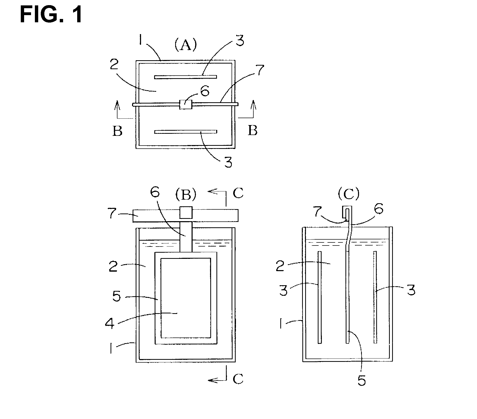
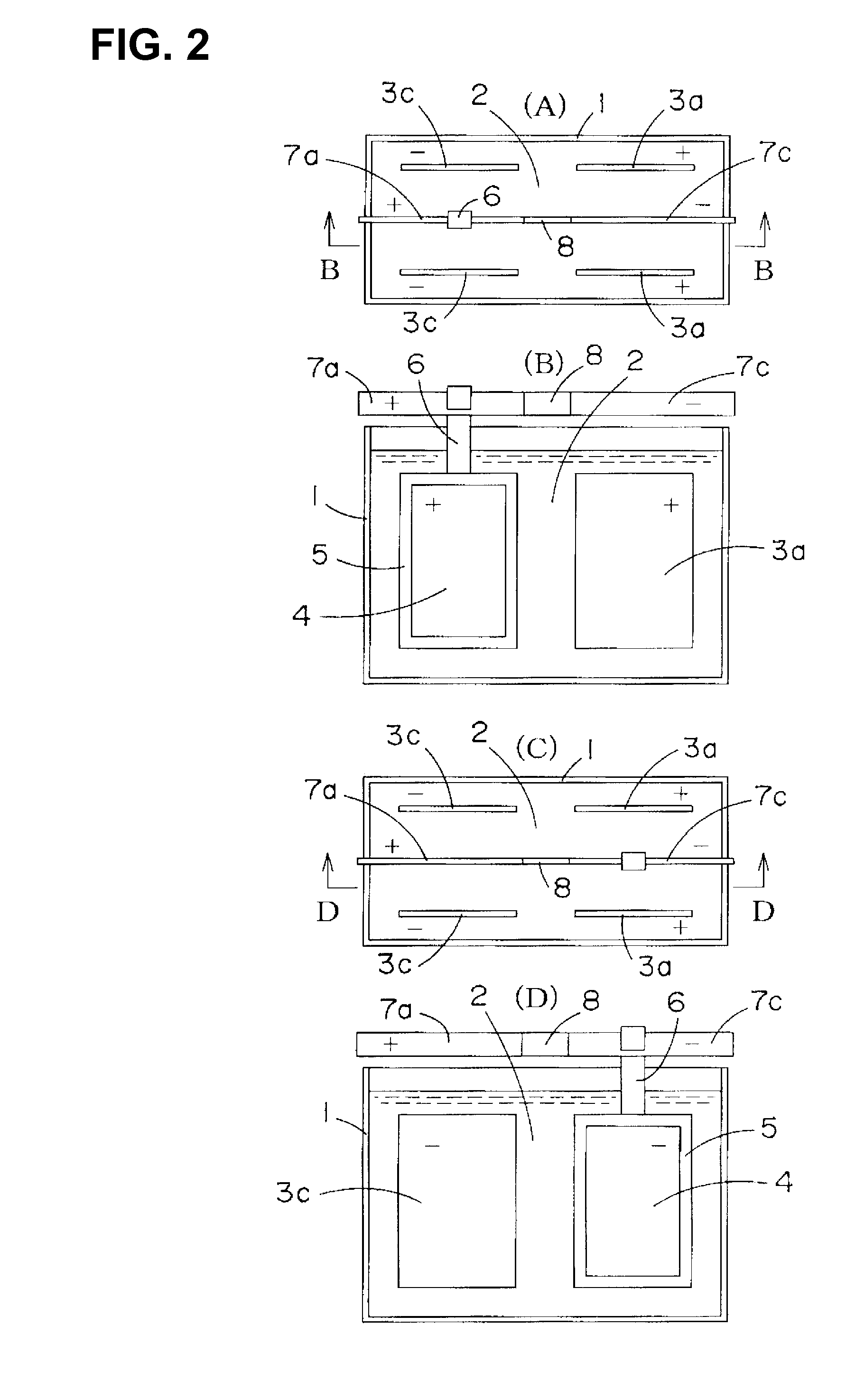
[0112]1 ELECTROLYTIC BATH[0113]2 ELECTROPLATING SOLUTION FOR PLATING COPPER ELECTRODE[0114]3a POSITIVE ELECTRODE[0115]3c NEGATIVE ELECTRODE[0116]4 COPPER PLATE WITH A ROUGHENED SURFACE[0117]5 FRAME BODY[0118]6 HANGER METAL FITTING[0119]7 BUS BAR[0120]7a BUS BAR FOR A POSITIVE ELECTRODE[0121]7c BUS BAR FOR A NEGATIVE ELECTRODE[0122]8 INSULATING BAR
Login to view more PUM
| Property | Measurement | Unit |
|---|---|---|
| Temperature | aaaaa | aaaaa |
| Temperature | aaaaa | aaaaa |
| Height | aaaaa | aaaaa |
Abstract
Problems to be Solved: To provide a process for roughening both sides of a copper plate by forming a protrusion with a fine bump shape on the both sides of the copper plate, and then to provide a process for a deterioration of an electroplating solution for plating copper to become hard to progress therein.
Means for Solving the Problems: First of all, there is designed to be arranged electrodes (3, 3) as a similar pole for therebetween to be opposed to each other in an electroplating copper solution 2, and then to be arranged a copper plate 4 at therebetween. And then at first there becomes to be performed an anodic treatment for generating a copper fine particles on both surfaces of the copper plate 4, by performing an electrolytic process with the copper plate 4 as a positive electrode and the electrodes 3 as negative electrodes. And then thereafter there becomes to be performed a cathodic treatment, by performing an electroplating of copper with the copper plate 4 as a negative electrode and the electrodes 3 as positive electrodes, for the copper fine particles to be fixed onto the surfaces of the copper plate 4. Furthermore, there becomes to be formed the above mentioned protrusion with the fine bump shape thereon, by performing the anodic treatment and then the cathodic treatment as not less than one cycle thereof.
Description
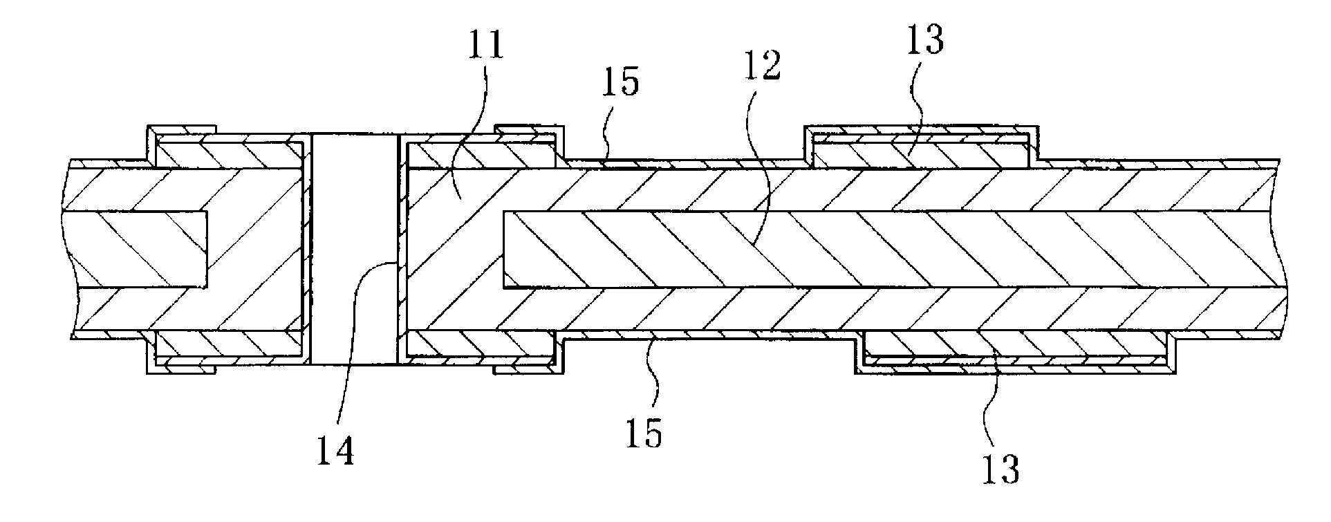
TECHNICAL FIELD[0001]The present invention relates to a method of producing a copper plate with a roughened surface used for a metal core of a metal core circuit board, a device for producing the copper plate with the roughened surface, and the copper plate with the roughened surface.BACKGROUND ART[0002]A metal core circuit board includes a metal plate with good thermal conductivity embedded in an insulating substrate, thereby improving heat uniformity and heat dissipation. The embedded metal plate improves a thermal characteristic of the circuit board. Hence, it is possible to flow a larger amount of an electric current even in a similar circuit pattern, thereby reducing a size of a circuit, a peripheral component, or the like.[0003]FIG. 15 is a cross sectional view showing an example of the metal core circuit board. In the figure, 11 designates an insulating substrate (a prepreg hardened through pressing and heating); 12 designates a metal plate embedded in the insulating substrat...
Claims
Login to view more Application Information
Patent Timeline
 IPC IPC(8): B32B3/10C25D17/10
CPCC25D3/38Y10T428/12361C25D5/34C25F3/02H05K1/056H05K3/384H05K2201/0355H05K2203/0307H05K2203/0723H05K2203/1572C25D5/02C25D7/00H05K3/0085Y10S205/92C25D5/18C25D5/48C25D17/00C25D5/10C25D5/617C25D5/605
Inventor WATANABE, HAJIMEISHIHAWA, SADAOYAMAMOTO, KIYOTERUIMAI, TAKAHIROOYOSHI, TOSHIHIRO
Owner FURUKAWA ELECTRIC CO LTD
- R&D Engineer
- R&D Manager
- IP Professional
Why Eureka
- Industry Leading Data Capabilities
- Powerful AI technology
- Patent DNA Extraction
Try Eureka
Browse by: Latest US Patents, China's latest patents, Technical Efficacy Thesaurus, Application Domain, Technology Topic.
© 2024 PatSnap. All rights reserved.Legal|Privacy policy|Modern Slavery Act Transparency Statement|Sitemap