Methods and moulds for use in fabricating side-ported microneedles

a technology of side-porting and microneedles, which is applied in the direction of manufacturing tools, foundry moulding apparatus, foundry patterns, etc., can solve the problems of microneedles that are too soft, too brittle (made of silicon or glass), and/or too expensive,

Inactive Publication Date: 2010-12-02
AGENCY FOR SCI TECH & RES
View PDF34 Cites 77 Cited by
  • Summary
  • Abstract
  • Description
  • Claims
  • Application Information

AI Technical Summary

Problems solved by technology

Existing microneedle fabrication techniques tend to produce microneedles that are too soft (made of polymeric materials), too brittle (made of silicon or glass) and / or too costly, and / or tend to be too unreliable.
Most prior art needles have openings at the tips of the needles, which means they must be of a minimum width there, so limiting their sharpness.
Further, as the injected fluid passes out through the axial direction of the needle it faces larger tissue back pressure, requiring a greater force to inject the fluid successfully.

Method used


Image

  • Methods and moulds for use in fabricating side-ported microneedles
  • Methods and moulds for use in fabricating side-ported microneedles
  • Methods and moulds for use in fabricating side-ported microneedles

Examples


first embodiment

Alternative Geometries and Other Variations of the First Embodiment

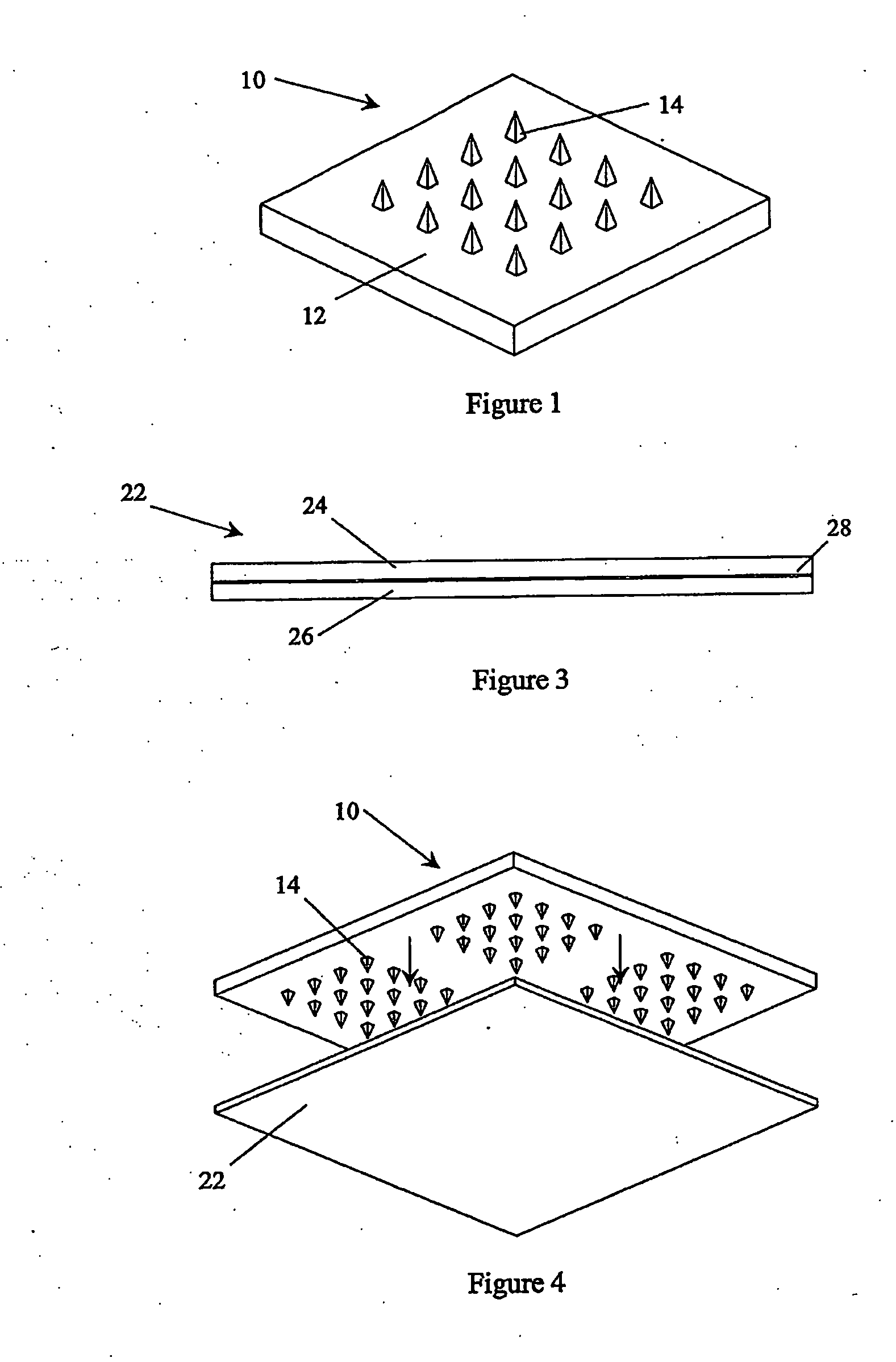
[0076]The microneedle mould plate 22, used to make the microneedle mould 40, is shown in the above embodiment (with reference to FIGS. 1 to 5) as being thicker than the height of the master mould needles 14. Alternatively, the thickness of the microneedle mould plate 22 and the height of the master mould needles 14 may be the same. The height of the master mould needles 14 may even be greater than the thickness of the microneedle mould plate 22. In the hot-pressing process, the extra height of the master mould needles 14 would then be accommodated into recesses of the lower plate of the hot press or into recesses into an extra plate on top of the lower plate of the hot press. In this manner, the recesses 30 (as shown in FIGS. 5 to 10) in the microneedle mould 40 become through-holes. This can improve the throwing power in the later electroforming step.

[0077]In the above-described embodiment, the side-port forming cha...

second main embodiment

[0102]A second main embodiment for making microneedles with side openings is now described. This method does not use two or more stacked embossing sheets as in the above-described first main embodiment and its variations. Instead the anomalies in the microneedle layer are introduced through the production process in the master mould.

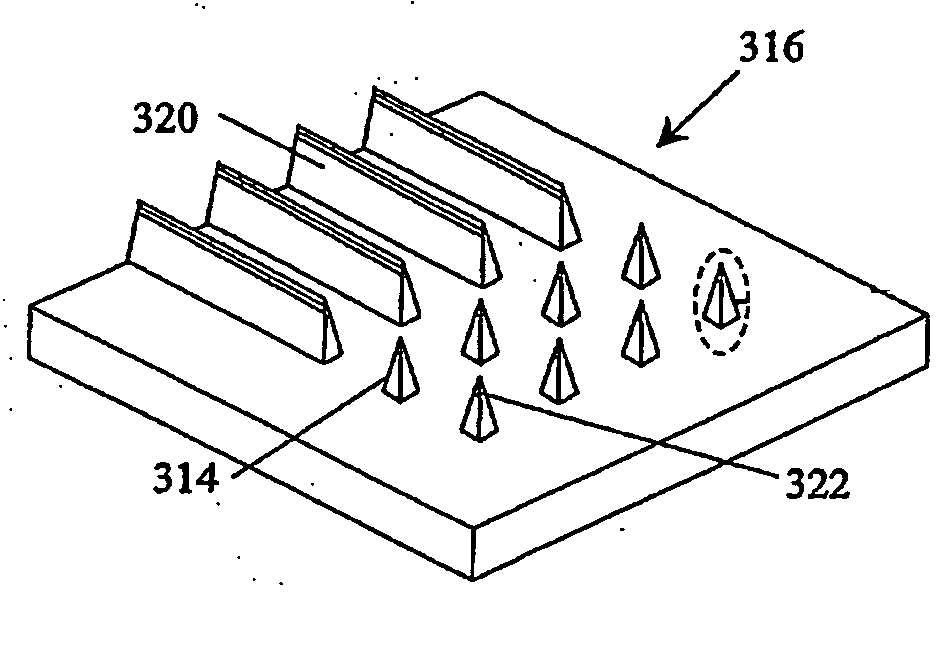
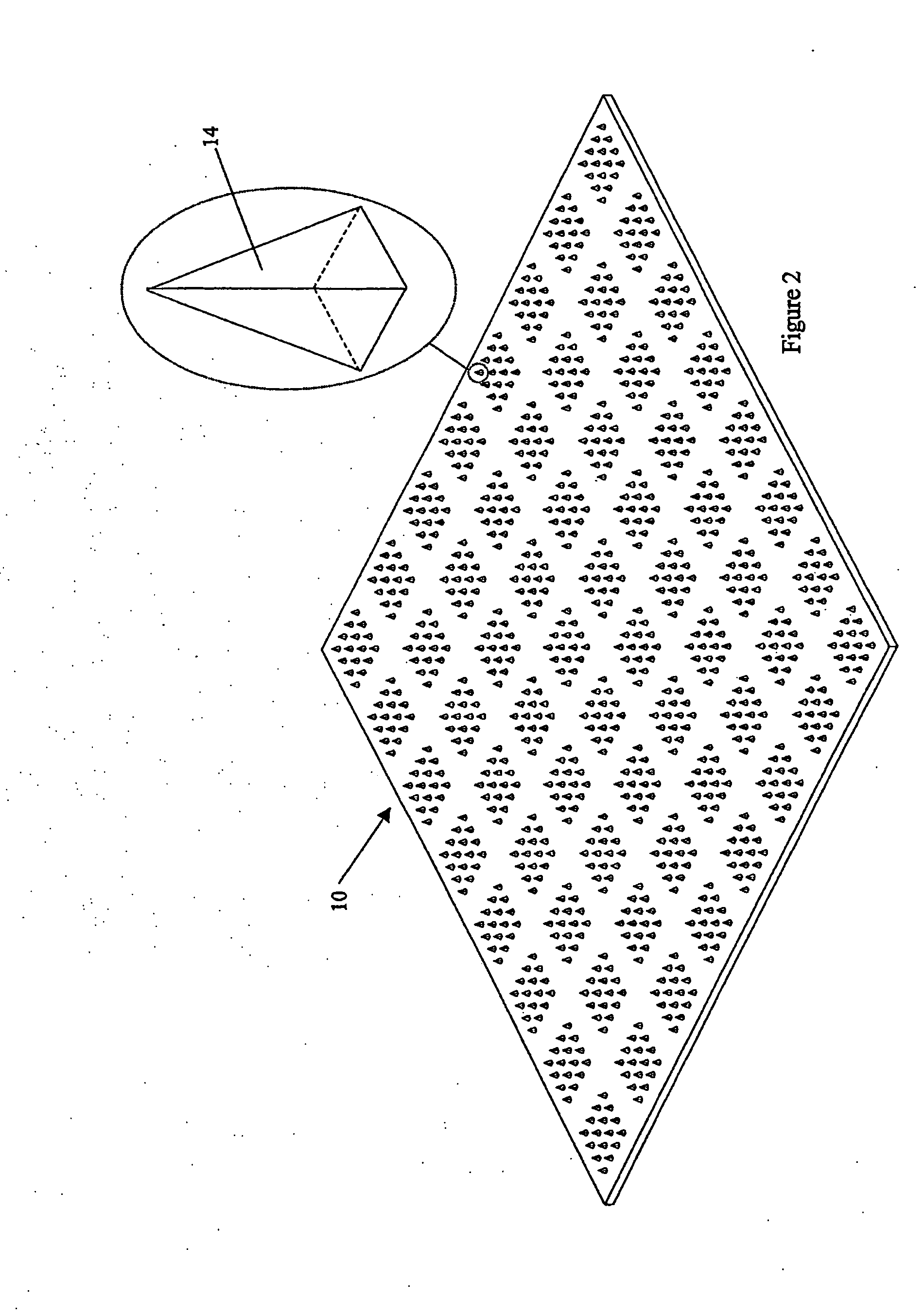
[0103]During the production of the master mould, a short part of one side of each master mould needle is made normal to the base surface of the master mould. The variant master mould may, for instance be made by way of a similar process to that employed to make the master mould of FIGS. 1 and 2. Such a process is now described with reference to FIGS. 21A to 21D.

[0104]FIG. 21A is a side view of a tool steel plate 316 after a first cut, in a similar manner to the first cut made to produce the part formed master mould of FIG. 19B (although producing a slightly blunter ridge in this embodiment). A first parallel set of ridges 320 has been produced. However, ...


PUM

PropertyMeasurementUnit
diameteraaaaaaaaaa
diameteraaaaaaaaaa
diameteraaaaaaaaaa

Abstract

Side-ported microneedles are produced from a suitably shaped microneedle mould (40). A microneedle mould base (32) is made with a number of microneedle mould recesses (30) in it. One surface of the microneedle mould base (32) is coated with a seed layer (34). The microneedle mould base (32) contains two microneedle mould sheets (24, 26), which are separated to gain access to an internal surface of one of the microneedle mould sheets (24, 26). Side-port forming channels (38) are formed on one of the internal surfaces, intersecting with the recesses (30) within the relevant microneedle mould sheet (24). The two microneedle mould sheets (24, 26) are placed back together and joined together as a unitary microneedle mould (40). The microneedles are formed in the recesses (30) by depositing a microneedle layer (44) therein and on the surface with the seed layer (34). The microneedle layer (44) fails to deposit at side-port forming holes (42) where the side-port forming channels (38) intersect the recesses (30), which result in side-ports (46) in the moulded microneedles (52).

Description

FIELD OF THE INVENTION[0001]The present invention relates to side-ported microneedles, that is microneedles with an opening in at least one side surface. In particular it relates to methods and moulds for use in the fabrication of side-ported microneedles, for instance in strays, and to the so-fabricated side-ported microneedles.BACKGROUND TO THE INVENTION[0002]Microneedles are small needles, typically in the range of from 1 (micron) to 3 mm long and from 10 nm to 1 mm in diameter at their bases, although the ranges can be wider, for instance up to 10 mm long and 2 mm at their bases. Microneedles typically have applications in biomedical devices, for instance for transdermal drug delivery. Existing microneedle fabrication techniques tend to produce microneedles that are too soft (made of polymeric materials), too brittle (made of silicon or glass) and / or too costly, and / or tend to be too unreliable. For transdermal drug delivery applications, where penetration of the outer skin (str...

Claims


Application Information

Patent Timeline
Patent Type & Authority Applications(United States)
IPC IPC(8): A61M5/00B22C9/22B29C33/42C25D1/00A61M37/00B29C33/00B29C33/30B29C33/38B29C33/40B29C33/56B29C59/02B81C99/00
CPCA61M37/0015A61M2037/003A61M2037/0053B29C33/0061B29C33/301B29C33/3857B29C33/40B29C33/424B29C33/56B29C59/026B29C2791/001B29C2793/0009B29L2031/756B29L2031/759B81B2201/055B81C99/009Y10T29/49986Y10T29/4998Y10T29/49984Y10T29/49988Y10T29/49885Y10T29/49982C25D1/02
Inventor XU, YUANWANG, MINGHUACHEN, MEI MALI, ZHONGLILIM, CHEE YENTAN, PEI YING JOYCE
Owner AGENCY FOR SCI TECH & RES
Why Eureka
Try Eureka