
Hydrogen filling apparatus and hydrogen filling method

Active Publication Date: 2010-12-09
HONDA MOTOR CO LTD
View PDF23 Cites 97 Cited by
  • Summary
  • Abstract
  • Description
  • Claims
  • Application Information

AI Technical Summary

Benefits of technology

[0009]It is an object of the present invention to provide a hydrogen filling apparatus and a hydrogen filling method which are capable of calculating and displaying a more accurate time needed to complete a hydrogen filling process when a hydrogen tank is filled with hydrogen, for thereby improving convenience for the operator.
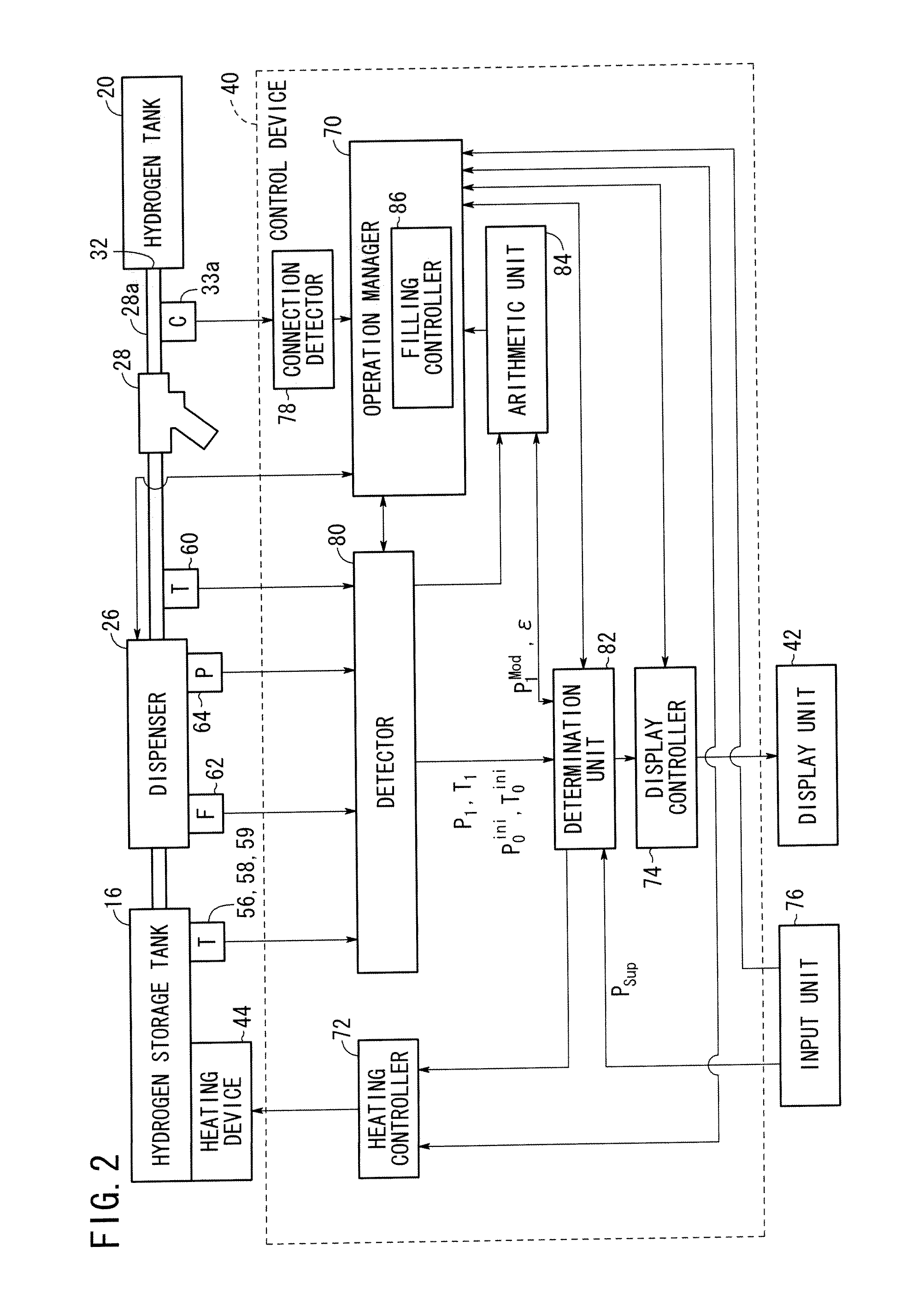
[0012]With above arrangement, after the hydrogen tank has started to be filled with hydrogen, the hydrogen filling process is temporarily stopped, and the time needed to fill the hydrogen tank is calculated based on the temperature and the pressure that are detected while the hydrogen filling process is being temporarily stopped. Therefore, the time needed to fill the hydrogen tank can be calculated depending on the temperature and the pressure detected while the hydrogen filling process is being temporarily stopped, and thus the time can be calculated more accurately. Further, the calculated time is displayed on the display unit, so that it is visualized in real time for the operator. Therefore, the hydrogen filling apparatus is more convenient to use.
[0013]The hydrogen filling process may include an initial filling stage before the hydrogen filling process is stopped for the predetermined time and a normal filling stage in which the hydrogen filling process is resumed after the temperature and the pressure are detected while the hydrogen filling process is being stopped. Thus, the temperature and the pressure in the hydrogen tank can easily be measured while the hydrogen filling process is being stopped between the initial filling stage and the normal filling stage.
[0014]The hydrogen filling apparatus may include a hydrogen storage tank for storing hydrogen to be charged into the hydrogen tank, and a heating device for heating the hydrogen storage tank when the temperature of the hydrogen storage tank drops below a predetermined temperature. In this case, the heating device is capable of preventing a pipe joint of the hydrogen storage tank from suffering an undue temperature drop in the hydrogen filling process, making it possible to discharge hydrogen from the hydrogen storage tank under a higher pressure. Therefore, the time required to fill the hydrogen tank can be shortened.
[0015]A pre-filling pressure in the hydrogen tank may be detected before the hydrogen tank starts to be filled with hydrogen, and a hydrogen leakage from the hydrogen tank may be detected based on the pre-filling pressure and the detected values of the temperature and the pressure, and is displayed on the display unit. Consequently, a hydrogen leakage from the hydrogen tank can quickly be detected and indicated to the operator reliably.
[0016]Alternatively, a pre-filling temperature and a pre-filling pressure in the hydrogen tank may be detected before the hydrogen tank starts to be filled with hydrogen, a volume of the hydrogen tank may be calculated based on the pre-filling temperature, the pre-filling pressure, and the detected values, and the time is calculated based on the calculated volume and a hydrogen flow rate. With this arrangement, the time needed to fill the hydrogen tank can be calculated accurately depending on the actual volume of the hydrogen tank. The hydrogen filling apparatus is highly convenient and versatile to use, as it can quickly and accurately calculate the time needed to fill the hydrogen tank even if the hydrogen tank has different volumes and remaining volumes for different vehicles.

Problems solved by technology

Though the disclosed apparatus is advantageous in that it can reduce the time required to fill the tank with the high-pressure gas because the temperature of the tank is prevented from increasing, the operator finds it hard to recognize the time needed to complete the filling process.
As the physical quantity tends to fluctuate, the accuracy with which to calculate the predicted time until the completion of the filling process is likely to decrease.

Method used


Image

  • Hydrogen filling apparatus and hydrogen filling method
  • Hydrogen filling apparatus and hydrogen filling method
  • Hydrogen filling apparatus and hydrogen filling method

Examples


Embodiment Construction

[0023]A hydrogen filling method according to a preferred embodiment of the present invention in relation to a hydrogen filling apparatus for carrying out the hydrogen filling method will be described in detail below with reference to the accompanying drawings.

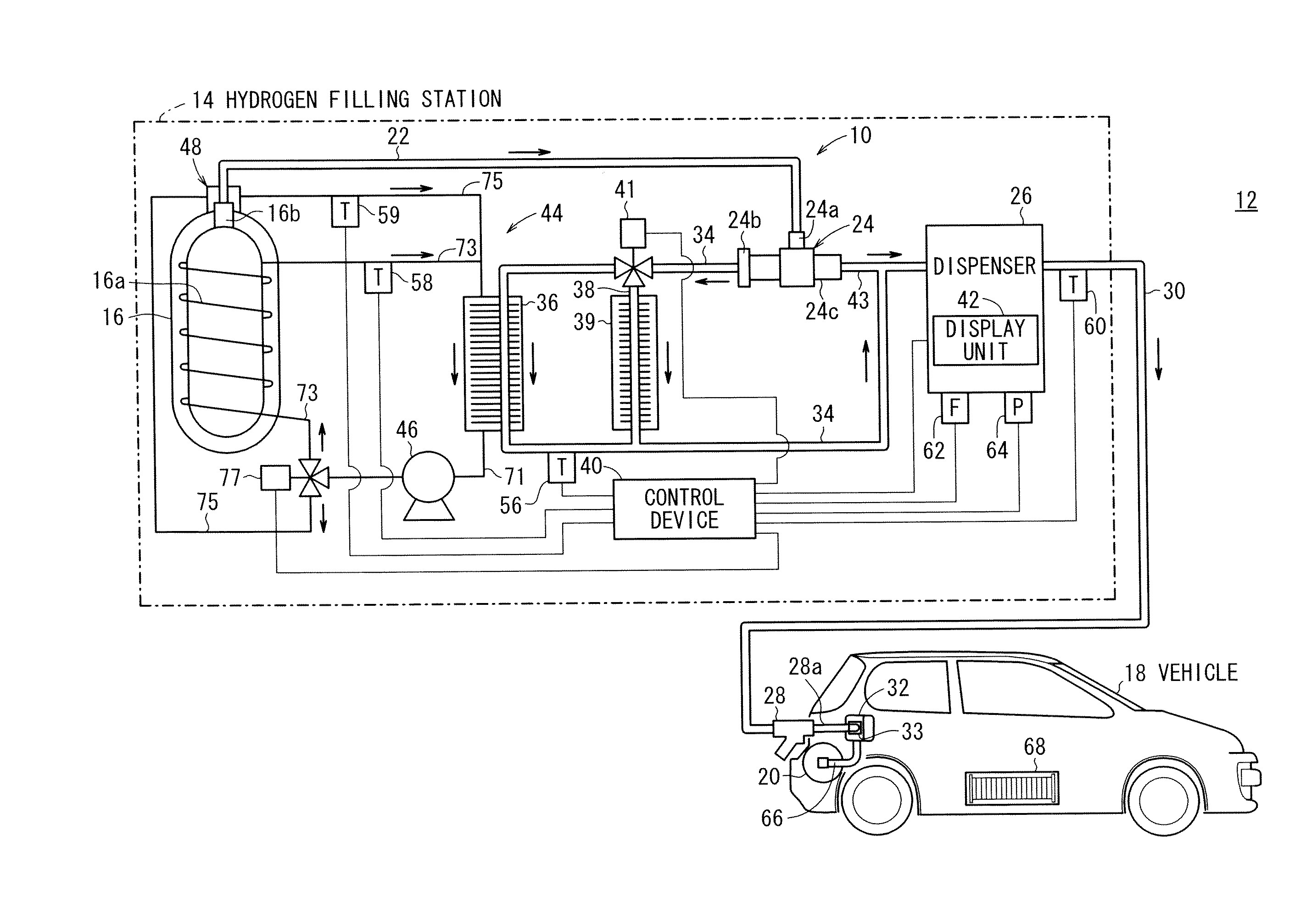
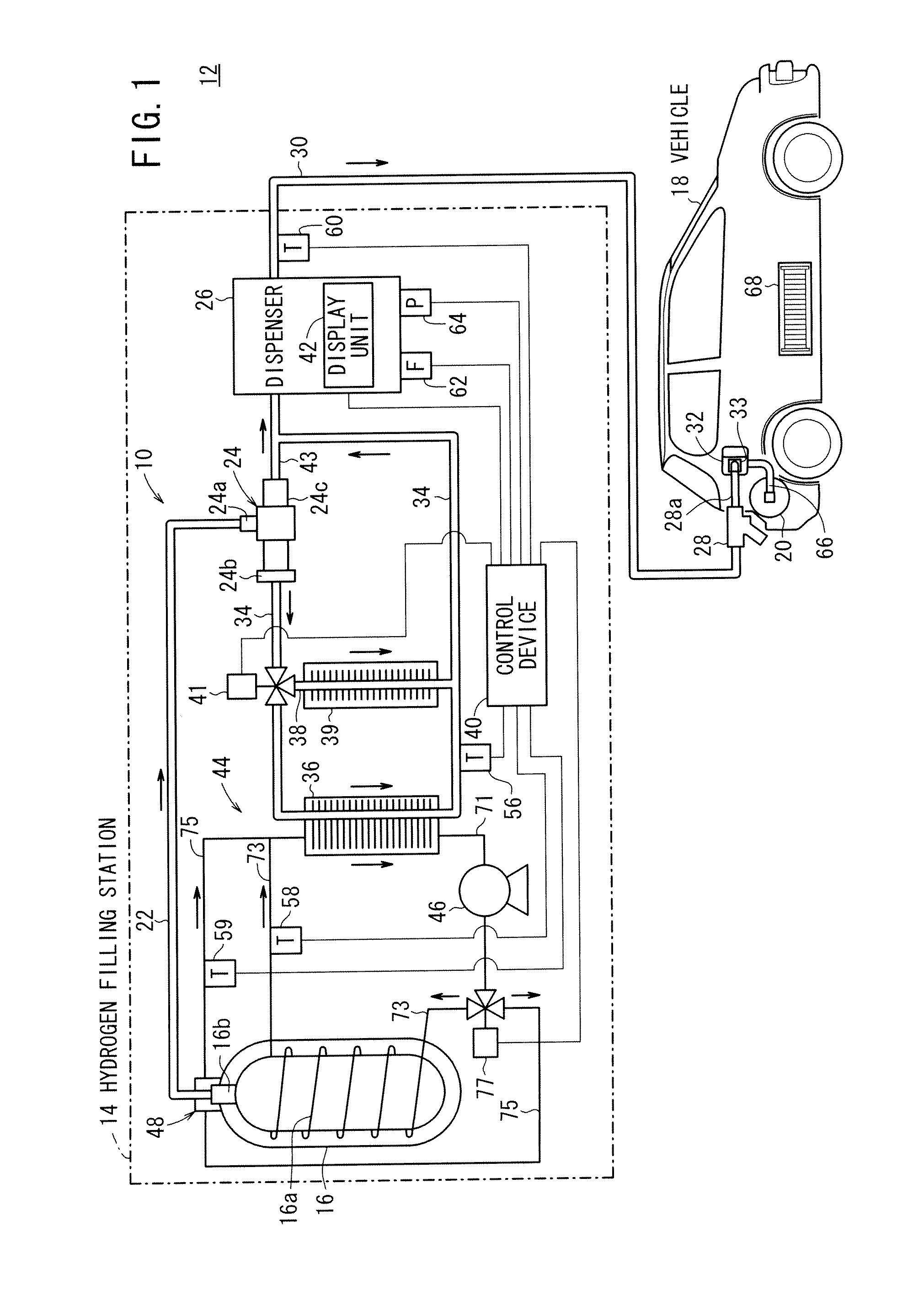
[0024]FIG. 1 is a schematic diagram of a hydrogen filling system 12 incorporating a hydrogen filling apparatus 10 according to an embodiment of the present invention. In FIG. 1, the dual lines represent a piping through which hydrogen (hydrogen gas) flows, the thicker solid lines a coolant piping through a coolant as a heat medium flows, and the thinner solid lines signal lines.

[0025]The hydrogen filling system 12 serves as a system for filling, using the hydrogen filling apparatus 10, a hydrogen tank 20 mounted on a fuel cell vehicle 18 with high-pressure hydrogen (hydrogen gas) that is stored in a hydrogen storage tank 16 in a hydrogen filling station 14. The hydrogen storage tank 16 may comprise a cradle of hydrogen containe...


PUM

PropertyMeasurementUnit
Temperatureaaaaaaaaaa
Pressureaaaaaaaaaa

Abstract

A hydrogen filling apparatus fills a hydrogen tank, for example, mounted on a fuel cell vehicle with hydrogen stored in a hydrogen storage tank. After the hydrogen tank has started to be filled with hydrogen in a hydrogen filling process, the hydrogen filling process is stopped for a predetermined time, and a temperature and a pressure in the hydrogen tank are detected while the hydrogen filling process is being stopped. Thereafter, a time needed to fill the hydrogen tank with a predetermined amount of hydrogen is calculated based on detected values of the temperature and the pressure, and the calculated time is displayed on a display unit.

Description

CROSS-REFERENCE TO RELATED APPLICATION[0001]This application is based upon and claims the benefit of priority from Japanese Patent Application No. 2009-138623 filed on Jun. 9, 2009, of which the contents are incorporated herein by reference.BACKGROUND OF THE INVENTION[0002]1. Field of the Invention[0003]The present invention relates to a hydrogen filling apparatus and a hydrogen filling method for filling a hydrogen tank with hydrogen to be supplied to a fuel cell or the like.[0004]2. Description of the Related Art[0005]Fuel cells for generating electrical energy by way of an electrochemical reaction between hydrogen and oxygen are supplied with hydrogen (hydrogen gas) as a fuel from a hydrogen tank. The hydrogen tank stores hydrogen under a predetermined high pressure and is located near the fuel cell. The hydrogen tank is usually filled with hydrogen supplied from a hydrogen storage tank which stores hydrogen under a higher pressure.[0006]Japanese Laid-Open Patent Publication No. ...

Claims


Application Information

Patent Timeline
IPC IPC(8): B65B3/04B65B1/30
CPCY02E60/321F17C2270/0184F17C2201/0109F17C2201/054F17C2203/0621F17C2205/0376F17C2221/012F17C2223/0153F17C2223/035F17C2225/0153F17C2225/033F17C2227/0341F17C2227/0348F17C2227/0355F17C2227/0386F17C2227/039F17C2250/032F17C2250/043F17C2250/0439F17C2250/0443F17C2250/0478F17C2250/0495F17C2250/0621F17C2250/0694F17C2260/025F17C2260/032F17C2265/065F17C5/06Y02E60/32
Inventor UEMURA, TAKURO
Owner HONDA MOTOR CO LTD
Learn More