Wireless IC device, electronic apparatus, and method for adjusting resonant frequency of wireless IC device

a wireless ic device and wireless technology, applied in the field of wireless ic devices, can solve the problems of increasing cost and increasing size, and achieve the effect of improving gain

Active Publication Date: 2010-12-09
MURATA MFG CO LTD
View PDF90 Cites 88 Cited by
  • Summary
  • Abstract
  • Description
  • Claims
  • Application Information

AI Technical Summary

Benefits of technology

[0027]According to the present invention, an existing electrode on the circuit board can be used as an antenna, and thus it is unnecessary to dispose an antenna as a separate component, thereby achieving miniaturization of t...

Problems solved by technology

However, because the RFID tag includes a dedicated antenna, a process of fabricating an antenna is required, lead...

Method used


Image

  • Wireless IC device, electronic apparatus, and method for adjusting resonant frequency of wireless IC device
  • Wireless IC device, electronic apparatus, and method for adjusting resonant frequency of wireless IC device
  • Wireless IC device, electronic apparatus, and method for adjusting resonant frequency of wireless IC device

Examples


first preferred embodiment

See FIGS. 8 and 9

[0109]The following will describe wireless IC devices according to first to fourteenth preferred embodiments of the present invention. In these preferred embodiments, a loop electrode is formed by an opening formed in a ground electrode, as described in the above-mentioned second and fourth basic preferred embodiments (see FIGS. 3 and 5).

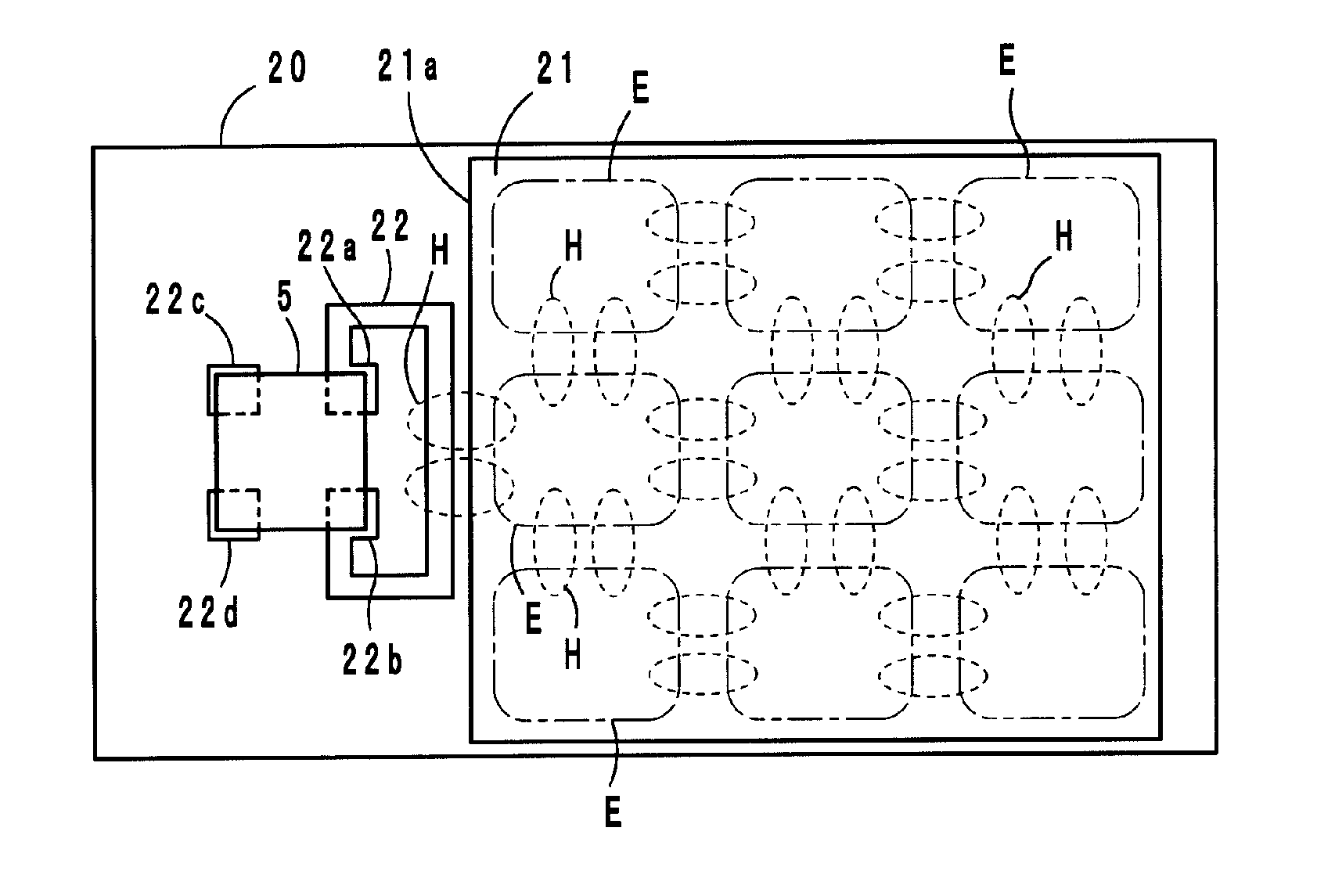
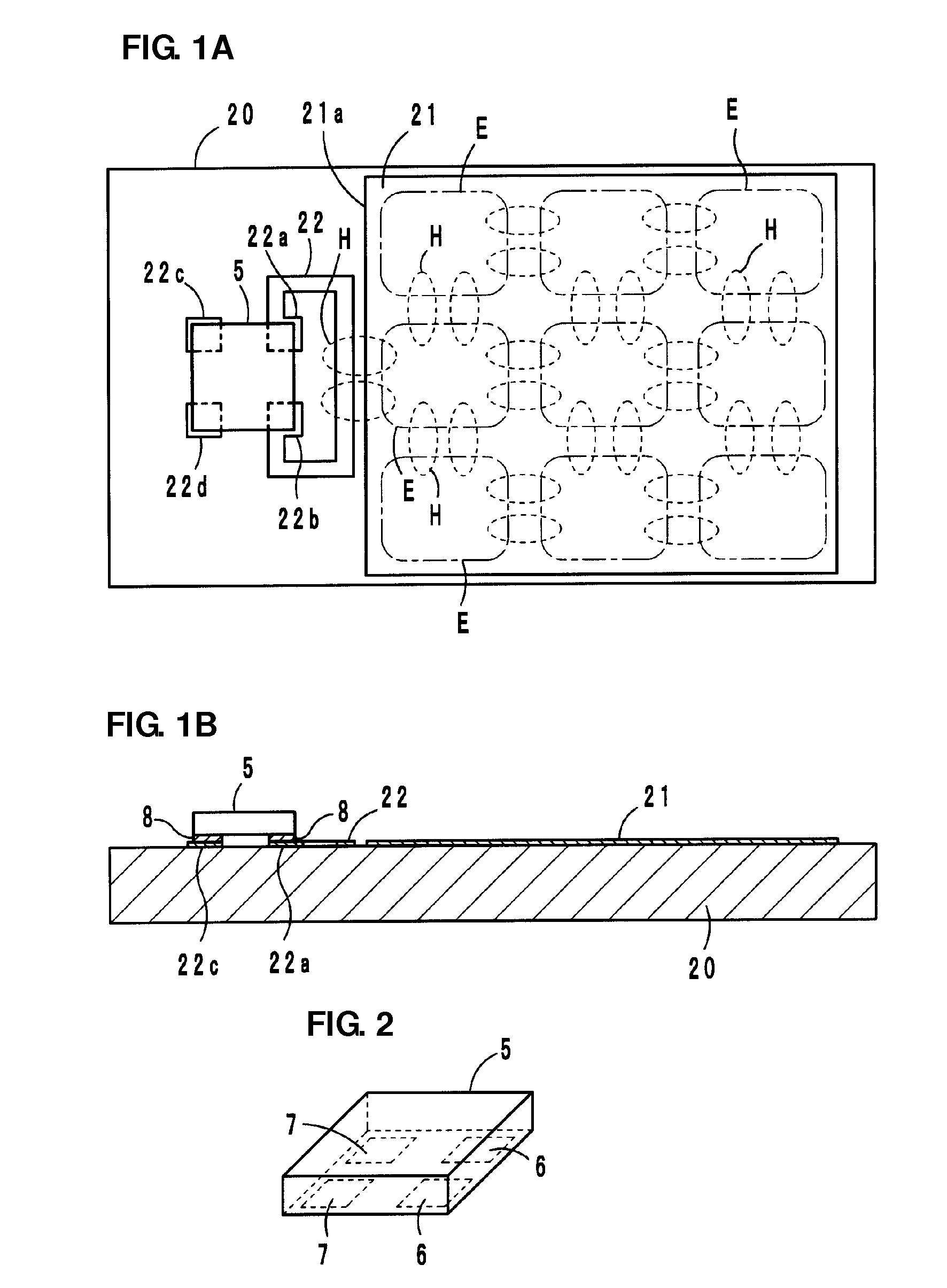
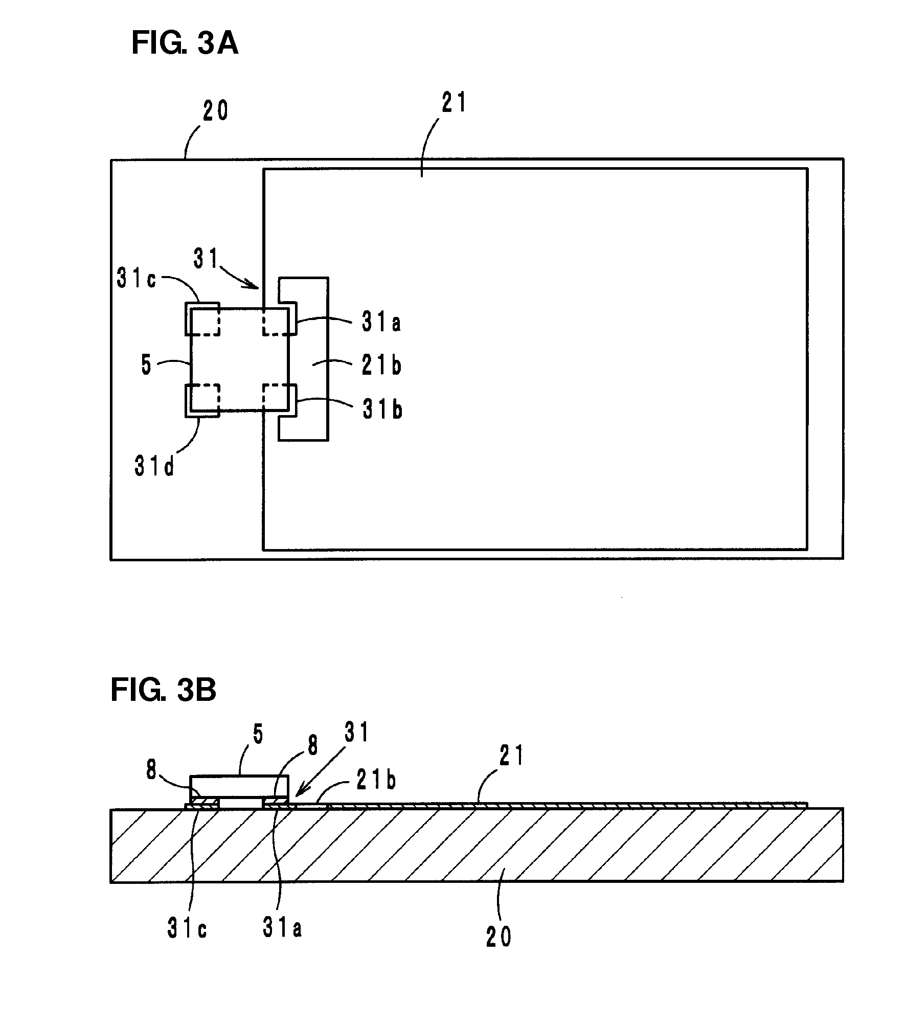
[0110]In the wireless IC device according to the first preferred embodiment, as shown in FIGS. 8 and 9, by forming the opening 21b at one side of the ground electrode 21 provided on the printed wiring circuit board 20, the loop electrode 31 is provided around the opening 21b, and the connecting electrodes 31a and 31b are coupled to the wireless IC chip 5 or the electromagnetic coupling module 1.

[0111]The ground electrode 21 that functions as an antenna is formed with slits 23a and 23b for adjusting the resonant frequency thereof. If the slits 23a and 23b are not formed, the ground electrode 21 resonates in a resonant mode in which b...

second preferred embodiment

See FIG. 10

[0115]In a wireless IC device according to a second preferred embodiment, as shown in FIG. 10, the ground electrode provided on the printed wiring circuit board 20 is formed with slits 23c and 23d for adjusting the resonant frequency thereof. By forming the slits 23c and 23d at the side opposite to the side at which the wireless IC chip 5 or the electromagnetic coupling module 1 is disposed, the resonant mode can be long, and even with the small-size ground electrode 21, the resonant frequency can be lowered so as to be close to the frequency used in the RFID system. Thus, the gain is improved.

third preferred embodiment

See FIG. 11

[0116]In a wireless IC device according to a third preferred embodiment, as shown in FIG. 11, the ground electrode 21 is formed with the slit 23a. By the one slit 23a, the resonant mode can be short, and the resonant frequency can be increased so as to be close to the frequency used in the RFID system. Thus, the gain is improved.


PUM

PropertyMeasurementUnit
Dielectric polarization enthalpyaaaaaaaaaa
Electrical conductivityaaaaaaaaaa
Electrical inductanceaaaaaaaaaa

Abstract

A wireless IC device and an electronic apparatus are obtained, which can achieve miniaturization and improve the gain of a radiator plate (electrode) without providing a dedicated antenna. A wireless IC device is provided, in which a loop electrode is provided in a ground electrode provided on a printed wiring circuit board, and in which a wireless IC chip that processes a transmission/reception signal or an electromagnetic coupling module is coupled to the loop electrode. The ground electrode is coupled to the wireless IC chip or the electromagnetic coupling module via the loop electrode, and transmits or receives a high-frequency signal. The ground electrode is formed with a slit for adjusting a resonant frequency thereof.

Description

BACKGROUND OF THE INVENTION[0001]1. Field of the Invention[0002]The present invention relates to a wireless IC device, and, more particularly, to a wireless IC device having a wireless IC chip used in an RFID (Radio Frequency Identification) system, an electronic apparatus including the wireless IC device, and a method for adjusting a resonant frequency of a wireless IC device.[0003]2. Description of the Related Art[0004]In recent years, an RFID system has been developed as an article management system, which includes: a reader / writer that generates an induction field; and an IC chip (also referred to as IC tag or wireless IC chip) that has stored predetermined information therein and is attached to an article, a container, or the like, and noncontact communication is established between the reader / writer and the IC chip to transmit the information therebetween.[0005]Japanese Unexamined Patent Application Publication (Translation of PCT Application) No. 11-515094 discloses an RFID t...

Claims


Application Information

Patent Timeline
IPC IPC(8): G06K19/077H01P11/00
CPCH01Q7/00H01Q9/40H05K1/16H01Q1/2225Y10T29/49016H01L2224/16225H01L2224/73204H01Q1/38H01Q9/285H01Q1/48
Inventor KATAYA, TAKESHIKATO, NOBORUISHINO, SATOSHIIKEMOTO, NOBUOKIMURA, IKUHEISHIROKI, KOJIDOKAI, YUYA
Owner MURATA MFG CO LTD
Why Eureka
Try Eureka