Test apparatus and test method

a test apparatus and test method technology, applied in the direction of individual semiconductor device testing, pulse characteristics measurement, instruments, etc., can solve the problems of difficult implementation of multichannel measuring devices in high density, difficult to perform mask tests for mass production testing, and long time-consuming to measure signal waveforms

Active Publication Date: 2010-12-09
ADVANTEST CORP
View PDF14 Cites 23 Cited by
  • Summary
  • Abstract
  • Description
  • Claims
  • Application Information

AI Technical Summary

Benefits of technology

[0010]Therefore, it is an object of an aspect of the innovations herein to provide a test apparatus and a test method, which are capable of overcoming the above drawbacks accompanying the related art. The above and other objects can be achieved by combinations described in the independent claims. The dependent claims define further advantageous and exemplary combinations of the innovations herein.
[0011]According to an aspect related to the innovations herein, provided is a test apparatus that tests a device under test. The test apparatus includes: a level comparing section that receives a signal under test output from the device under test and outputs a logical value, the logical value indicating a comparison result obtained by comparing a signal level of the signal under test with preset first threshold and second threshold; an acquiring section that acquires the logical value output from the level comparing section, according to a strobe signal supplied thereto; an expected value comparing circuit that determines whether the logical value acquired by the acquiring section corresponds to a preset expected value; and a threshold control section that sets an upper limit and a lower limit of a voltage of the eye mask to the level comparing section as the first threshold and the second threshold, when an eye mask test is performed for determining whether an eye opening of the signal under test is larger than a predefined eye mask. A test method relating to the above test apparatus is also provided.

Problems solved by technology

However, it is difficult to perform mask tests for the mass production test by an apparatus in which the separate measuring device, such as the sampling oscilloscope and the time interval analyzer is provided with the software for the mask test.
For example, when measuring with the multichannel, many oscilloscopes may be required, therefore, it is difficult to implement the measuring device with the multichannel in a high density.
In addition, since the signal waveforms are measured by equivalent sampling, it takes a long time to measure the signal waveforms.

Method used


Image

  • Test apparatus and test method
  • Test apparatus and test method
  • Test apparatus and test method

Examples


Embodiment Construction

[0026]Hereinafter, some embodiments of the present invention will be described. The embodiments do not limit the invention according to the claims, and all the combinations of the features described in the embodiments are not necessarily essential to means provided by aspects of the invention.

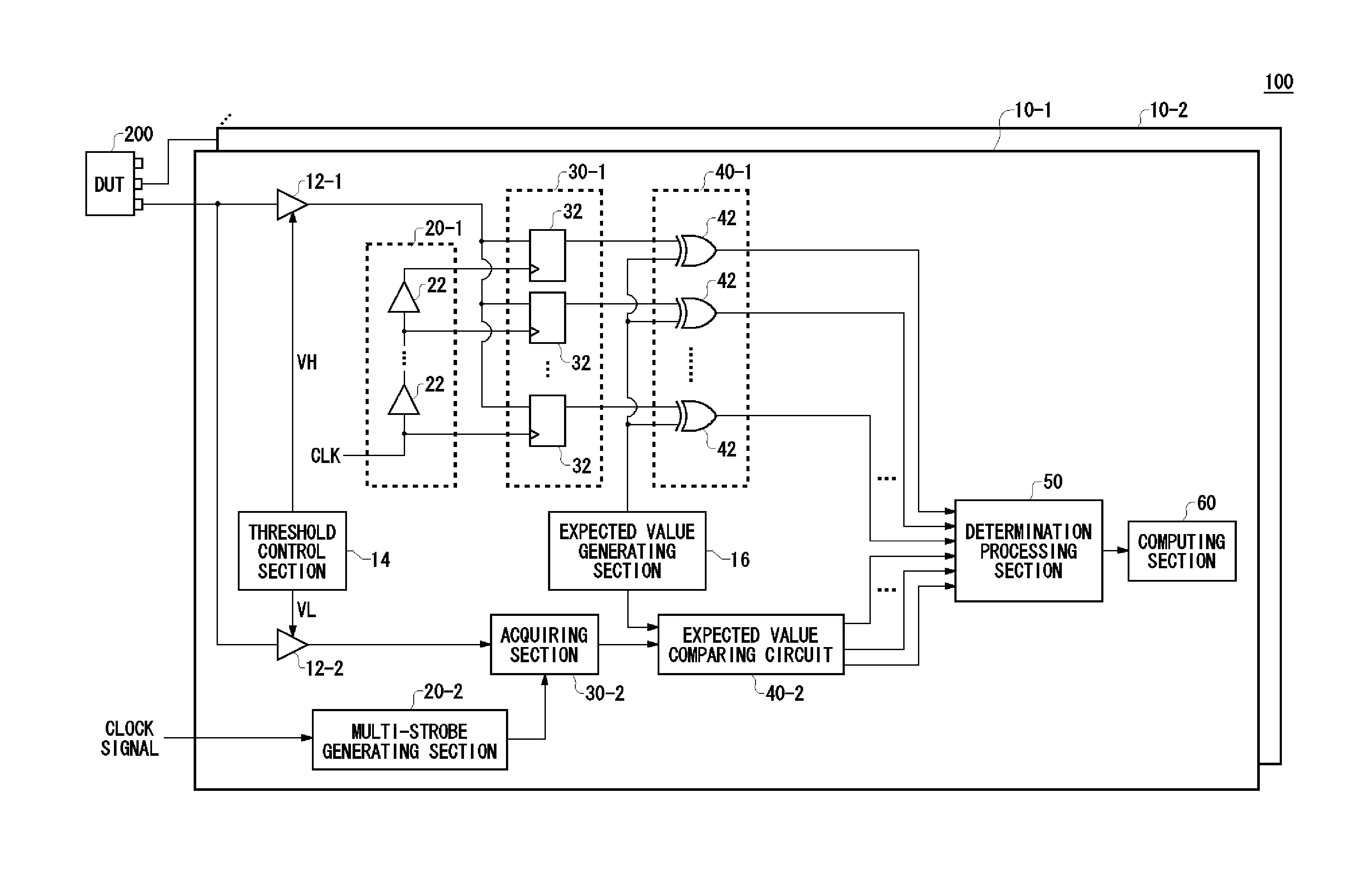
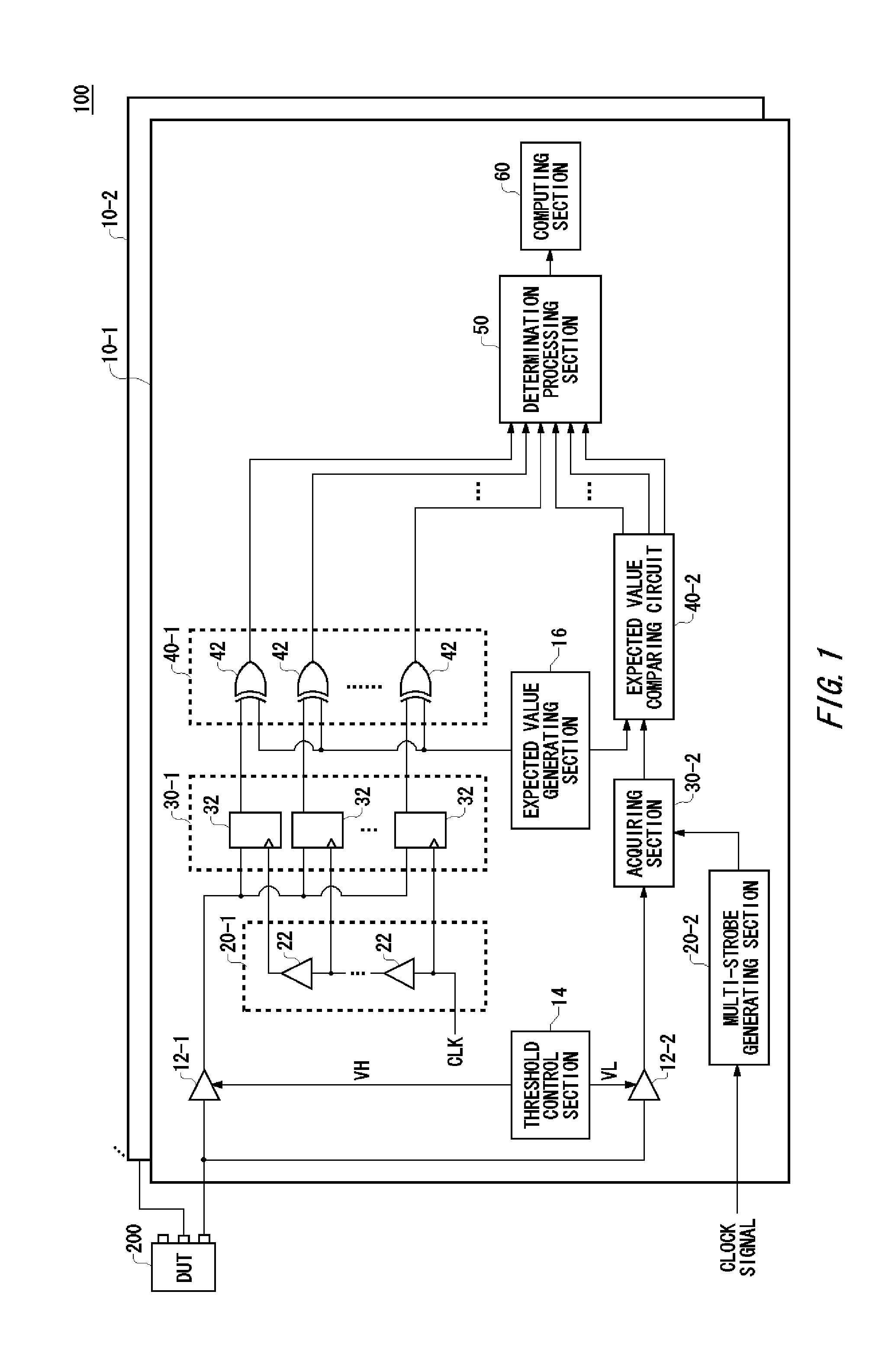
[0027]FIG. 1 shows an exemplary configuration of a test apparatus 100 according to an embodiment of the present invention. The test apparatus 100 tests a device under test 200 such as a semiconductor chip and has a plurality of measuring units 10. A signal under test output from the device under test 200 is input to each of the measuring units 10, and the measuring unit 10 measures the eye opening of the signal under test.

[0028]The measuring unit 10 according to the present embodiment generates a multi-strobe described later for each cycle of the signal under test to remove the dead band in the measurement without changing and scanning the phase of a strobe signal. That is, the measuring unit 1...


PUM


Abstract

Provided is a test apparatus for testing a device under test, including: a level comparing section that receives a signal under test output from the device under test and outputs a logical value, the logical value indicating a comparison result obtained by comparing a signal level of the signal under test with preset first threshold and second threshold; an acquiring section that acquires the logical value output from the level comparing section, according to a strobe signal supplied thereto; an expected value comparing circuit that determines whether the logical value acquired by the acquiring section corresponds to a preset expected value; and a threshold control section that sets an upper limit and a lower limit of a voltage of the eye mask to the level comparing section as the first threshold and the second threshold, when an eye mask test is performed for determining whether an eye opening of the signal under test is larger than a predefined eye mask.

Description

BACKGROUND[0001]1. Technical Field[0002]The present invention relates to a test apparatus and a test method for testing a device under test. More specifically, the present invention relates to a test apparatus and a test method for testing an degree of eye opening of a signal which is output from the device under test.[0003]2. Related Art[0004]A test of a quality of output waveforms is one item in tests for a device under test such as a semiconductor chip. For example, such test may be performed by causing the device under test to output a pseudo random pattern to measure the degree of eye opening of an eye diagram of an output signal. In order to measure the degree of eye opening in a timing direction, jitter of the edge of the output signal is measured, meanwhile a mask test is performed in order to measure the degrees of eye opening both in the direction of timing and in the direction of voltage level.[0005]The mask test is to measure whether all waveform data of the output signa...

Claims


Application Information

Patent Timeline
Patent Type & Authority Applications(United States)
IPC IPC(8): G01R31/26
CPCG01R29/027G01R31/31932G01R31/31703G01R31/3004G01R29/02G01R31/28
Inventor WATANABE, DAISUKEOKAYASU, TOSHIYUKI
Owner ADVANTEST CORP
Why Eureka
Try Eureka