Method and apparatus for cross-talk cancellation

a cross-talk cancellation and cross-talk technology, applied in the direction of transmission, frequency-division multiplex details, electrical equipment, etc., can solve the problem of cross-talk between the transmission and receiver chain, transmission signal, transmission signal, etc., to remove or reduce the transmit cross-talk signal

Inactive Publication Date: 2010-12-09
QUALCOMM TECH INT
View PDF19 Cites 28 Cited by
  • Summary
  • Abstract
  • Description
  • Claims
  • Application Information

AI Technical Summary

Benefits of technology

[0018]In view of the above from a first aspect the present invention provides a method of cross-talk cancellation in a transceiver having a transmitter which signal processes and transmits a transmit signal, and a receiver which receives and signal processes a receive signal, the receive signal including therein a transmit cross-talk signal being at least a partial representation of the transmit signal, the method comprising: obtaining the transmit signal to be signal processed and transmit by the transmitter; signal processing the transmit signal to produce a cross-talk cancellation signal, the signal processing comprising applying to the transmit signal one or more signal processing operations which emulate the generation of the transmit cross-talk signal from the transmit signal in the receiver; and combining the cross-talk cancellation signal with the receive signal containing the transmit cross-talk signal to thereby substantially remove or reduce the transmit cross-talk signal from the receive signal.
[0019]From a further aspect there is also provided a transceiver comprising: a transmitter which signa

Problems solved by technology

In frequency division duplex systems where both the transmission chain and the receiver chain are active simultaneously, the problem of cross-talk between the transmission and receiver chain can therefore occur.
In spite of chip planning and careful insulation between the transmitter chain and the receiver chain, the transmitted signal, due to its significantly higher signal power, can severely distort any received signal.
The worst kind of distortion is clipping, where the transmitted signal saturates the transistors in the receiver chain.
Clipping introduces non-linearities which may make restoration of the desired received signal impossible.
In direct converting receivers particularly cross-talk is a problem, since here second order distortion introduced by the receive mixer 22 results in a cross-talk signal which is spectrally overlapping the receiver signal ba

Method used


Image

  • Method and apparatus for cross-talk cancellation
  • Method and apparatus for cross-talk cancellation
  • Method and apparatus for cross-talk cancellation

Examples


first embodiment

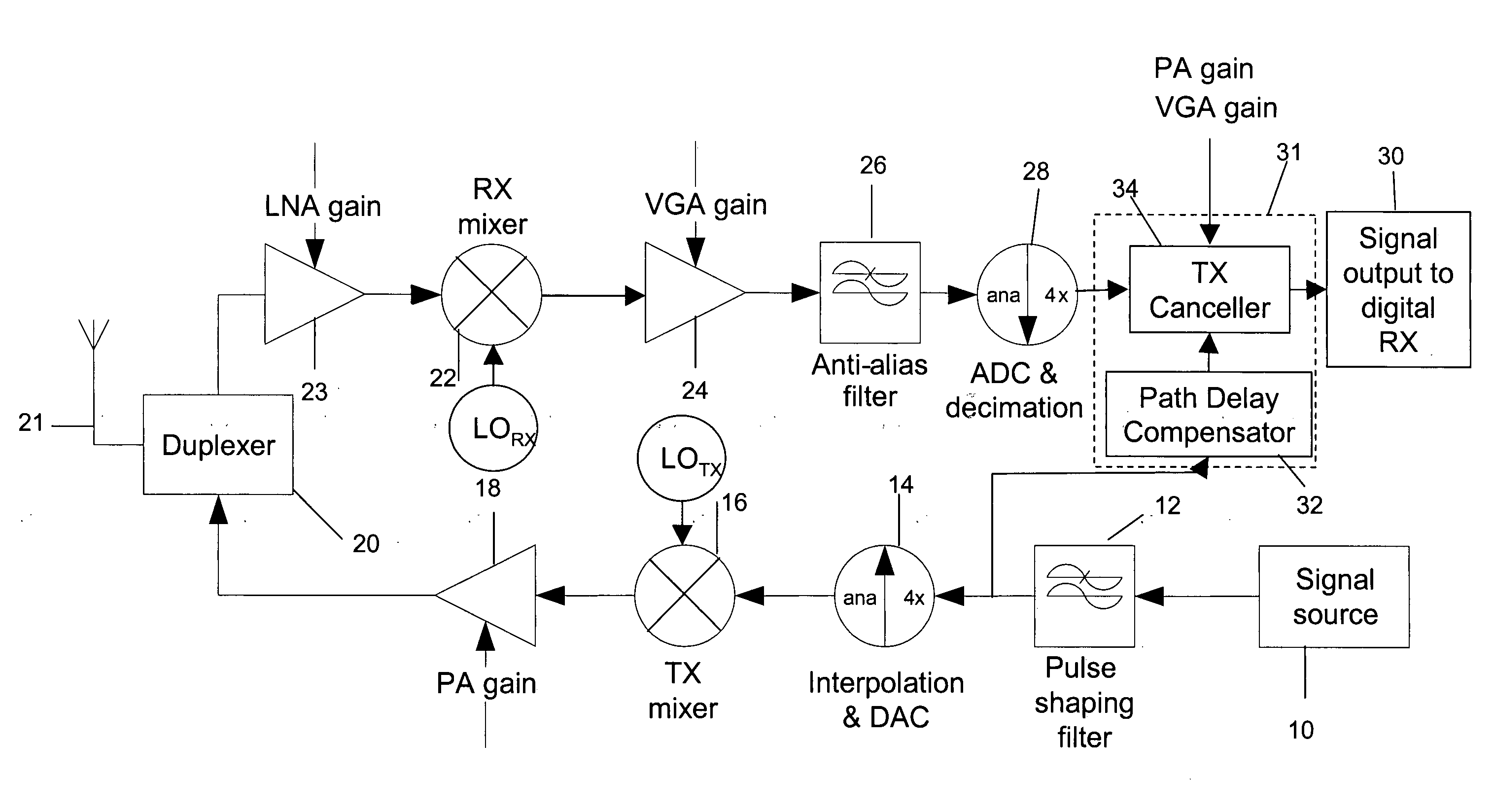
[0045]FIG. 3 is a block diagram of the internal processing performed by the cross-talk canceller 34 in the invention. In this embodiment, the receiver gain and transmitter gain control signals are not required, and need not be fed to the cross-talk canceller 34.

[0046]With reference to FIG. 3, the transmit signal is received at the “TX in” input, having been delayed by the path delay compensation block 32. The input transmit signal is then put into processing block 42, which acts to perform a squaring operation thereon. In this respect, it will be recalled that it is the square of the transmit signal which is the main cross-talk signal of interest, due to the second order inter-modulation distortion product, or self mixing in the receive mixer 22. The squared transmit signal, u(n) is then fed to a subtractor 44.

[0047]The second input to the subtractor 44 is the received signal, d(n), received at the cross-talk canceller 34 from down-sampler 20. It will be appreciated here that the re...

second embodiment

[0056]However, it should be noted that with a fixed filter transfer function such as present in filter 46, it is only possible to adapt the transmit signal to match the transmit cross-talk signal if the processing applied to the transmit cross-talk signal is substantially fixed i.e. the anti-alias filter 26 has a substantially fixed and known transfer function, and the gains applied to the transmit cross-talk signal in the transmit and receive amplifiers are constant. If any of these factors are variable, such as may often be the case with the gains applied in the transmitter power amplifier and receiver variable gain amplifier, or where the filter transfer function is not known, or varies over time, then the output signal y(n) from the filter 46 may not then accurately represent the transmit cross-talk signal at the point in the receiver signalling chain where the cross-talk canceller is located. To address the second of these problems, i.e. where the filter transfer function is no...

third embodiment

[0059]There remains, however, the problem of the gains which are applied to the receive signal, and hence the cross-talk signal, being variable. This presents problems even for an adaptive filter that the dynamic range of the filter taps needs to be very large to compensate for signal level changes. Additionally, the adaptation rate of the filter may not be quick enough to compensate for rapid gain changes. Therefore, in the third embodiment, described next, the filter 46 is supplemented by additional amplifiers, to replicate the transmitter and receiver amplifier gains applied to the transmit cross-talk signal.

[0060]A third embodiment of the invention is therefore shown in FIG. 5. In particular, FIG. 5 shows the arrangement of the cross-talk canceller 34 of the third embodiment, the remainder of the elements of the third embodiment being the same as described previously with respect to FIGS. 1 and 2.

[0061]As shown in FIG. 5 the cross-talk canceller 34 according to the third embodim...


PUM


Abstract

The present invention addresses the problem of a second (or higher) order representation of a transmit signal which is transmitted by a transceiver being mixed into the region of the frequency spectrum of interest to the transceiver receiver, such that it can not then be spectrally filtered out. At its most straightforward, in one embodiment of the invention this is achieved by providing a cross-talk cancellation unit which takes the transmit signal, and obtains the second (or higher) order representation thereof. This representation is then subtracted from the received signal before the signal is passed to the radio control receiver signal processing elements. However, in a more preferred arrangement a filter is also provided, to filter the second or higher order version of the transmit signal, prior to its being subtracted from the received signal. The filter basically takes out the effects of any other filtering or processing which has happened to the transmit signal in the receiver signal chain. This would be, for example, the filtering effects provided by the anti-aliasing filter in the receiver.

Description

TECHNICAL FIELD[0001]The present invention relates to a method and apparatus for cancelling cross-talk between the transmit and receive paths in a radio transceiver, and in particular for cancelling transmission cross-talk in the receiver.BACKGROUND TO THE INVENTION[0002]Direct converting transceivers are well known in the art. By “direct converting” it is meant that conversion is made directly from RF to baseband, without an intermediate frequency. Such direct converting transceivers may commonly be used in, for example, the radio of a mobile telephone, or the like. FIG. 1 illustrates the components of a typical direct converting transceiver which forms the basis of the present invention.[0003]With reference to FIG. 1, here a baseband signal 10 is fed into the transmit path of the transceiver. The baseband signal 10 is filtered by a pulse shaping filter such as a root raised cosine (RRC) filter 12 so as to limit the bandwidth and hence limit spurious emissions. The output of the pu...

Claims


Application Information

Patent Timeline
IPC IPC(8): H04J3/10
CPCH04B1/525
Inventor ASTROM, MAGNUS
Owner QUALCOMM TECH INT
Why Eureka
Try Eureka