Furnace and Process for Controlling the Oxidative State of Molten Materials

a technology of oxidative state and molten materials, which is applied in the direction of manufacturing tools, furniture, lighting and heating apparatus, etc., can solve the problems of unsatisfactory effects, unsatisfactory and/or convenient effects, and high purity of base materials, so as to improve the quality of molten materials and improve the clarity of float glass

Active Publication Date: 2010-12-16
AIR PROD & CHEM INC
View PDF53 Cites 52 Cited by
  • Summary
  • Abstract
  • Description
  • Claims
  • Application Information

AI Technical Summary

Benefits of technology

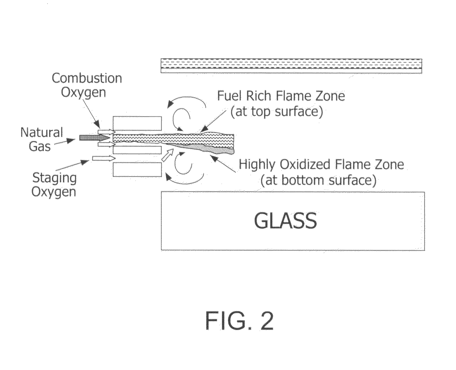
[0008]The instant invention can solve problems associated with conventional methods for obtaining molten materials by using, for example, flat-flame, staged combustion technology to influence the oxidation state of transition metal ions associated with a molten material. Influencing the oxidation state can impact the chemical and physical properties of the molten material (e.g., oxidizing iron ions to Fe(III)), in order to improve the quality of molten materials (e.g., improving the clarity of the float glass such as solar glass).

Problems solved by technology

In many industrial heating processes fired with fuel and oxidant, products of fuel combustion in the melting end of the furnace may interact or react with molten material and often cause undesirable effects.
For example, a fuel rich flame impinging over melting glass in a glass melting furnace is known to cause color change in glass product due to redox change of the glass melt exposed to the fuel rich flame.
However, base materials with a high degree of purity are expensive and thus not always desirable and / or convenient.
In other words, for example, the removal of iron from glass raw materials has certain practical and / or economical limits.

Method used


Image

  • Furnace and Process for Controlling the Oxidative State of Molten Materials
  • Furnace and Process for Controlling the Oxidative State of Molten Materials
  • Furnace and Process for Controlling the Oxidative State of Molten Materials

Examples


example 1

[0098]is a baseline example that represents the conventional air-firing float glass furnace with a firing rate of 46.89 MW (160 MMBTU / hr) and a pull rate of 670 MTPD of a soda-lime-silicate glass. FIG. 4 shows the simulated temperature profile in the mid-plane of the furnace (the y axis is Temperature in degrees Celsius and the x axis corresponds to the length of the furnace). As shown, the temperature is the highest in the middle section of the furnace, around the port 5 and 6. Because of this temperature distribution, natural convection exists in the glass melt, and as a result there is a spring zone just downstream port 6 (as illustrated in FIG. 5 wherein the ports correspond to the rectangular openings above the glass melt and are numbered from left to right). Fe2O3 (Fe3+) entered the charge end (the left-hand side of FIGS. 4 through 7) at a mass fraction of about 0.03%. As the temperature is increased, Fe2O3 is reduced to FeO (Fe2+) and O2 with the highest FeO and O2 concentrat...

example 2

[0099]represents on example with the oxygen-fuel burner is installed above the spring zone of the glass melt (as illustrated in FIG. 6). The burner is operated with a stoichiometric ratio of 200%. The additional oxygen from the oxygen-fuel burner provides an oxygen rich environment above the spring zone and helps to prevent the escape of the oxygen from the melt to combustion space above the melt. As a result, the glass FeO concentration at the furnace exit is reduced by about 35% when compared to the baseline example (Example 1).

example 3

[0100]represents a case where the oxygen burner is installed over the batch (as illustrated in FIG. 7). Because the lower temperature in the batch region, iron is more thermodynamically stable in its Fe3+ state, (and as a result oxygen concentration in the glass is relatively low), the reaction between Fe3+ and Fe2+ is slow, and the thermally activated diffusion of O2 into the glass melt is very small. Therefore the additional oxygen in the atmosphere does not provide any significant benefit in controlling the oxidation of the glass. The simulation shows the FeO concentration in the final production does not significantly change relative the example where there is no oxygen-fuel burner.

[0101]These examples show that desirable results in accordance with this invention can be achieved by locating an oxygen-fuel burner over the refining zone, and in particular, adjacent to or near the spring-zone of the furnace.


PUM

PropertyMeasurementUnit
velocityaaaaaaaaaa
transparentaaaaaaaaaa

Abstract

A method useful with oxy-fuel combustion and in a furnace which contains molten material, wherein either substoichiometric or superstoichiometric combustion and low velocity injection of fuel and primary and secondary oxidant in an oxy-fuel burner are carried out in an orientation which forms either a reducing or oxidizing atmosphere proximate the molten surface.

Description

CROSS-REFERENCE TO RELATED APPLICATIONS[0001]This application claims benefit of Provisional Application No. 61 / 186,418, filed Jun. 12, 2009. The disclosure of this application is hereby incorporated by reference.BACKGROUND OF THE INVENTION[0002]Certain aspects of this invention relate to staged, flat-flame combustion within a furnace which contains molten material such as glass to be affected by heat generated by the combustion. The combustion is also used to affect the oxidation state of the iron in the molten glass in the refining or fining section of the glass melting furnace.[0003]In many industrial heating processes fired with fuel and oxidant, products of fuel combustion in the melting end of the furnace may interact or react with molten material and often cause undesirable effects. For example, a fuel rich flame impinging over melting glass in a glass melting furnace is known to cause color change in glass product due to redox change of the glass melt exposed to the fuel rich...

Claims


Application Information

Patent Timeline
Patent Type & Authority Applications(United States)
IPC IPC(8): C03B5/00
CPCC03B5/235C03B5/2353C03B2211/62F23C6/045F23C2900/06041F23L7/007Y02E20/344Y02P40/57Y02P40/55Y02E20/34Y02P40/50C03B5/08
Inventor WATSON, MATTHEW JAMESHABEL, MICHAEL EDWARDLIEVRE, KEVIN ALANHE, XIAOYI
Owner AIR PROD & CHEM INC
Why Eureka
Try Eureka