Municipal bicycle sharing system

a bicycle sharing and municipal technology, applied in the field of transportation, can solve the problems of limiting the growth of business and logistical problems of users, and achieve the effect of reducing/eliminating the pilfering of bicycles

Inactive Publication Date: 2010-12-16
RZEPECKI S RYAN
View PDF25 Cites 52 Cited by
  • Summary
  • Abstract
  • Description
  • Claims
  • Application Information

AI Technical Summary

Benefits of technology

[0005]Additional features of the bicycle sharing system of the present invention include the capability to unlock the bicycle for use from a remote location by using a wireless communication device secured within a lockbox, making the use of kiosks or stands unnecessary. The lockbox will also include a global positioning system (GPS) tracking unit that tracks the real time position of each bike. The GPS receiver and wireless device will be powered by onboard battery(ies) that is / are recharged by a dynamic recharging means such as, for example, a bicycle hub dynamo that recharges the battery(ies) while the bicycle is in motion. The GPS / wireless communication system allows a computer-based, central monitoring and control system to track the position of each bicycle in the system, collect trip data for use by the system administrators and end users, and transmit unlock commands to the manually locked / remotely unlocked locking system on the bicycle when a valid request is received from a potential customer. This electronic locator system should also reduce / eliminate pilfering of bicycles utilized in the system.
[0010]The preferred lock system of the present invention comprises a) a scissor-clamp formed by a first arm and a second arm intertwined by a pivot post, each arm having a gripping claw at one end which grasps a seat tube of a bicycle and an extending finger at a distal end of the arm; b) a lockbox having a bottom wall and a lid, the bottom wall and the lid engaging the extending finger of each arm in a closed, latched position securing the extending fingers against movement thereof and preventing the scissor clamp from being removed from the seat tube of the bicycle. In addition, the lock system includes c) a U-shaped retainer having a first arm with a plurality of cylindrical protrusions, a second arm which can be extended outside the lockbox; d) a mechanical locking device which engages the first arm of the U-shaped retainer preventing relative movement between the U-shaped retainer and the lockbox; e) a first ear protruding from a lower side of the bottom of the lockbox on a first side of a wheel of the bicycle, the first ear having a first throughbore; f) a second ear protruding from a lower side of the bottom of the lockbox on a second side of the wheel of the bicycle, the second ear having a second throughbore which is aligned with the first throughbore; whereby the second arm of the U-shaped retainer is extended through the first and second aligned throughbores and the wheel of the bicycle immobilizing the bicycle. The U-shaped retainer can be extended about a post prior to the first arm being engaged by said mechanical locking device thereby securing and immobilizing the bicycle.
[0012]The first arm of the U-shaped retainer includes a plurality of annular protrusions on at least a portion of its length. The mechanical locking device, then, includes an extendable member having a plurality of teeth which interdigitate with the annular protrusions on the first arm to preclude movement thereof. A solenoid is attached to the extendable member to disengage said mechanical locking device responsive to an authorized signal from an electronic touch pad. At least one illuminated light is positioned in the lockbox and shines out through at least one portal on a rear surface of the lockbox to render the bicycle more visible. More preferably, the at least one illuminated light comprises at least two illuminated lights and the at least one portal comprises at least two portals on the rear surface of said the box.

Problems solved by technology

The requirement of such features limits the growth of the business since it requires land acquisition and installation of expensive infrastructure.
It also creates a logistical problem for users since the rented bicycle must be returned to one of a limited number of pre-determined locations.

Method used


Image

  • Municipal bicycle sharing system
  • Municipal bicycle sharing system
  • Municipal bicycle sharing system

Examples


Embodiment Construction

)

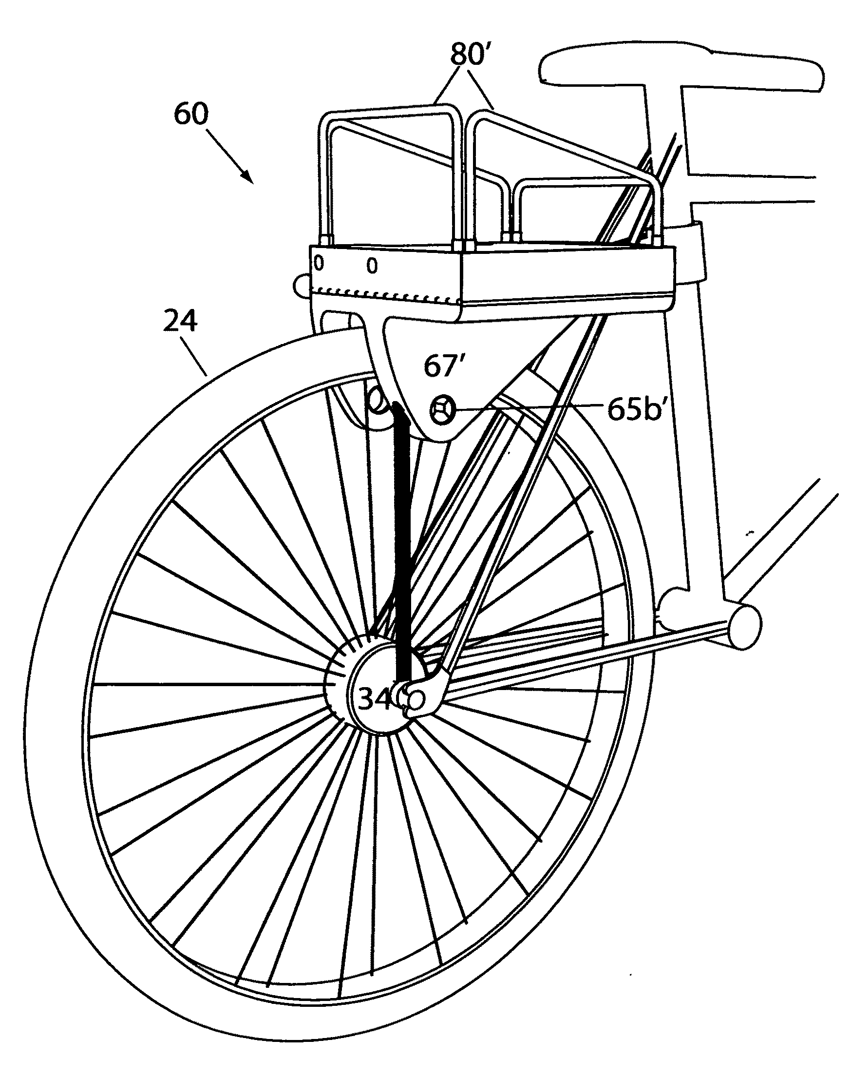
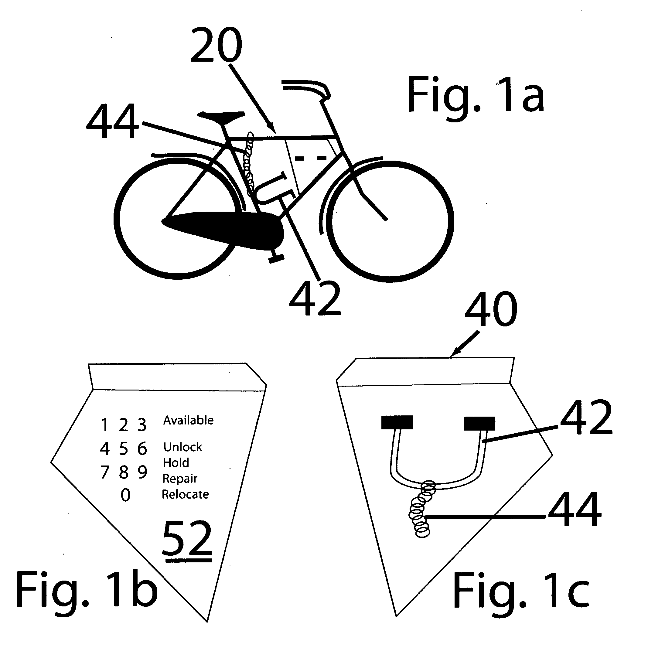
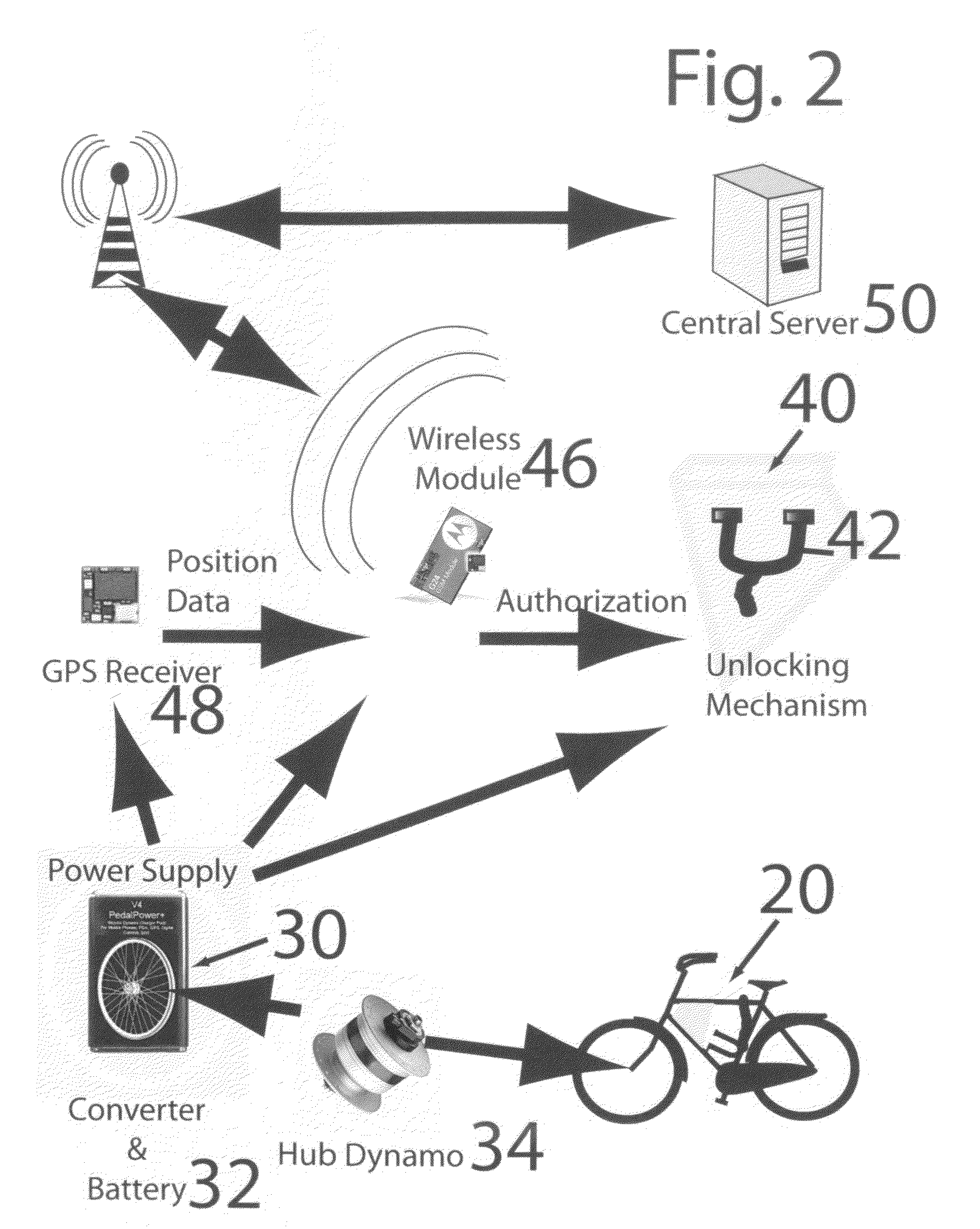
[0039]The two critical features of the stationless bicycle share system of the present invention are 1) an effective locking mechanism and, 2) the electronics package including the battery-powered GPS unit and the wireless communication device, the battery(ies) being recharged by a dynamic recharger such as an internal hub dynamo mounted on one of the wheels.

[0040]As depicted in FIG. 2, the components of the bike share system include a rugged, reliable bicycle 20, a rechargeable power supply 30 system including a power converter 31 and battery 32, a hub dynamo 34. One suitable bike is available from Worksman Cycles of New York City, N.Y., manufacturers of sturdy industrial cycles for over a century. It is preferred that the bicycle be painted with a retro-reflective powder coating of the type commercially available from Halo Coatings, a subsidiary of MKB LLC of Port Clinton, Ohio, under the trademark “Hi-Viz”. It is desired that the cycles used in the cycle share system to be marke...


PUM


Abstract

A bike share system with the flexibility to anchor the rental bike anywhere at the end of the trip employs a remotely operable lockbox which incorporates a wireless communication card with a GPS receiver. The lock system includes a scissor clamp for grasping the bicycle seat support post and a pair of extended fingers of the scissor clamp which are retained by the clamshell halves of the lockbox. One arm of a U-shaped retainer can be extended into throughbores of first and second ears positioned on opposing sides of the bicycle wheel to lock the wheel against rotation. A mechanical locking device has teeth which engage with protrusions on the other arm of the U-shaped retainer to prevent its movement relative to the lockbox maintaining the other arm in wheel immobilizing position.

Description

[0001]The present application is a continuation-in-part of U.S. patent application Ser. No. 12 / 456,227 filed Jun. 12, 2009.BACKGROUND AND SUMMARY OF THE INVENTION[0002]The present invention is directed to the field of transportation. More particularly, the present invention is directed to a stationless bicycle sharing system and method of conducting such a business from a remote location.[0003]The sustainability movement has spawned the growth of bicycle rental operations, as a means of improving mobility and reducing automobile dependence. The systems proposed thus far typically involve the provision of a locking station and a rental kiosk where credit card payment can be made. The requirement of such features limits the growth of the business since it requires land acquisition and installation of expensive infrastructure. It also creates a logistical problem for users since the rented bicycle must be returned to one of a limited number of pre-determined locations.[0004]The present...

Claims


Application Information

Patent Timeline
Patent Type & Authority Applications(United States)
IPC IPC(8): B62H5/00E05B71/00E05B47/00
CPCB62H5/145B62H5/20B62H2003/005G07F17/0057Y10T70/5872
Inventor RZEPECKI, S. RYAN
Owner RZEPECKI S RYAN
Why Eureka
Try Eureka