
Heat transfer tube

a technology of heat transfer tube and heat conductor, which is applied in the direction of heat exchange apparatus, stationary conduit assembly, light and heating apparatus, etc., can solve the problems of reduced heat transfer coefficient, reduced mechanical rigidity, and insufficient use of additional heat conducting materials to create heat transfer surfaces, etc., to achieve the effect of increasing the total heat transfer surface, increasing mechanical rigidity, and increasing mechanical rigidity

Inactive Publication Date: 2010-12-16
BUNDY REFRIGERATION
View PDF11 Cites 14 Cited by
  • Summary
  • Abstract
  • Description
  • Claims
  • Application Information

AI Technical Summary

Benefits of technology

[0012]Test measurements on a heat transfer tube in accordance with the invention showed that a heat transfer coefficient can be achieved that is higher than those of the above mentioned conventional evaporators and condensers.
[0014]In addition, because the wing-shaped protrusion is formed out of the tube material, differentials in the elongation of material caused by temperature variations are avoided. Consequently, paint cracks in a painted heat transfer tube can be completely avoided, and therefore the risk of corrosion can also be avoided.
[0015]In a preferred embodiment of the present invention, the tube extends along a centre line and the wing-shaped protrusion is formed into a twisting shape extending about the centre line. Preferably the wing-shaped protrusion forms a spiral around the centre line of the tube. In an alternative preferred embodiment the wing-shaped protrusion forms a wave shape along the tube. With a wing-shaped protrusion formed into such twisting shapes, the heat transfer through the wing-shaped protrusion can be further improved by the increased airflow. Due to this, the heat transfer coefficient will be further improved.
[0017]In a preferred embodiment of the present invention, the heat transfer tube is formed into a shape having at least two axially extending wing-shaped protrusions, and the wing-shaped protrusions are equally spaced around the wall of the tube. By this means, the total heat transfer surface can be fundamentally increased and the heat transfer can be more evenly distributed.
[0018]In some embodiments, the wing-shaped protrusion of the tube is pressed such that two different portions of the inside surface of the tube are in contact with each other. Thus, no gap exists between these two different portions. Such an arrangement provides the tube with increased mechanical rigidity, which is particularly useful for tubes with smaller wall thicknesses.
[0019]In other embodiments of the present invention the heat transfer tube has a main flow portion defining a main bore and the wing-shaped protrusion defines a gap that is open to the main bore. In this way, fluid flowing down the bore of the tube is able to pass into and out of the gap, so that heat transfer is further improved.

Problems solved by technology

A problem with the production of heat exchangers formed in such a manner, with this additional heat conductive material, is that it is very material and cost intensive.
A second problem is that the additional heat conducting materials used to create heat transfer surfaces are not all equally used in the heat transfer process.
This leads to a decrease of a heat transfer coefficient.
There is also a risk, especially for evaporators in which the heat transfer tube is formed of steel and painted for corrosion protection, that the painted layer will crack where the tube is contacted to the additional heat conductive material.
Consequently, corrosion is not avoidable where the cracking occurs.
However, the method produces only a very small increase of the heat transferring surface and so it has little effect on the heat transfer of the tube.

Method used


Image

  • Heat transfer tube
  • Heat transfer tube
  • Heat transfer tube

Examples


Embodiment Construction

FIG. 1

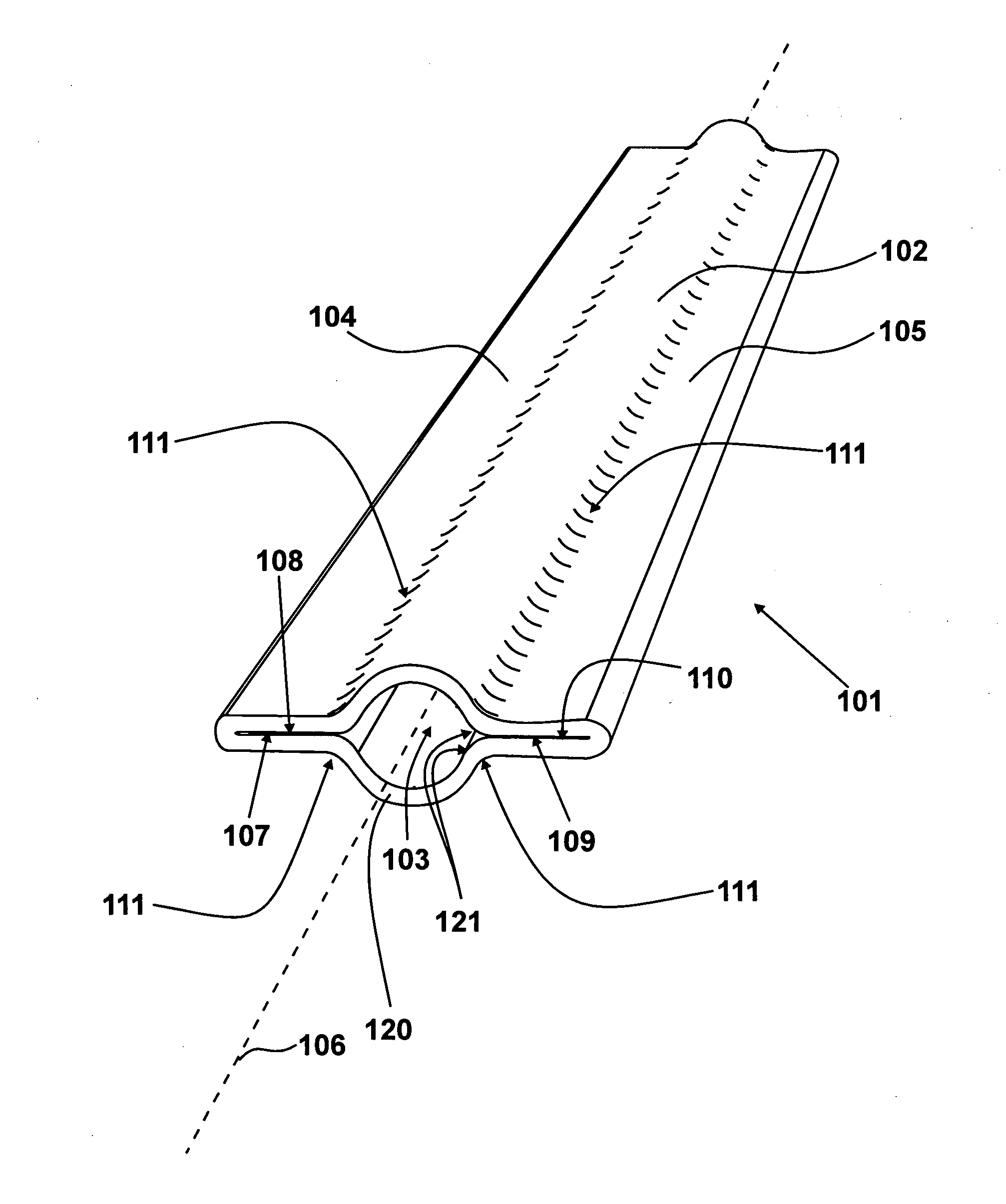
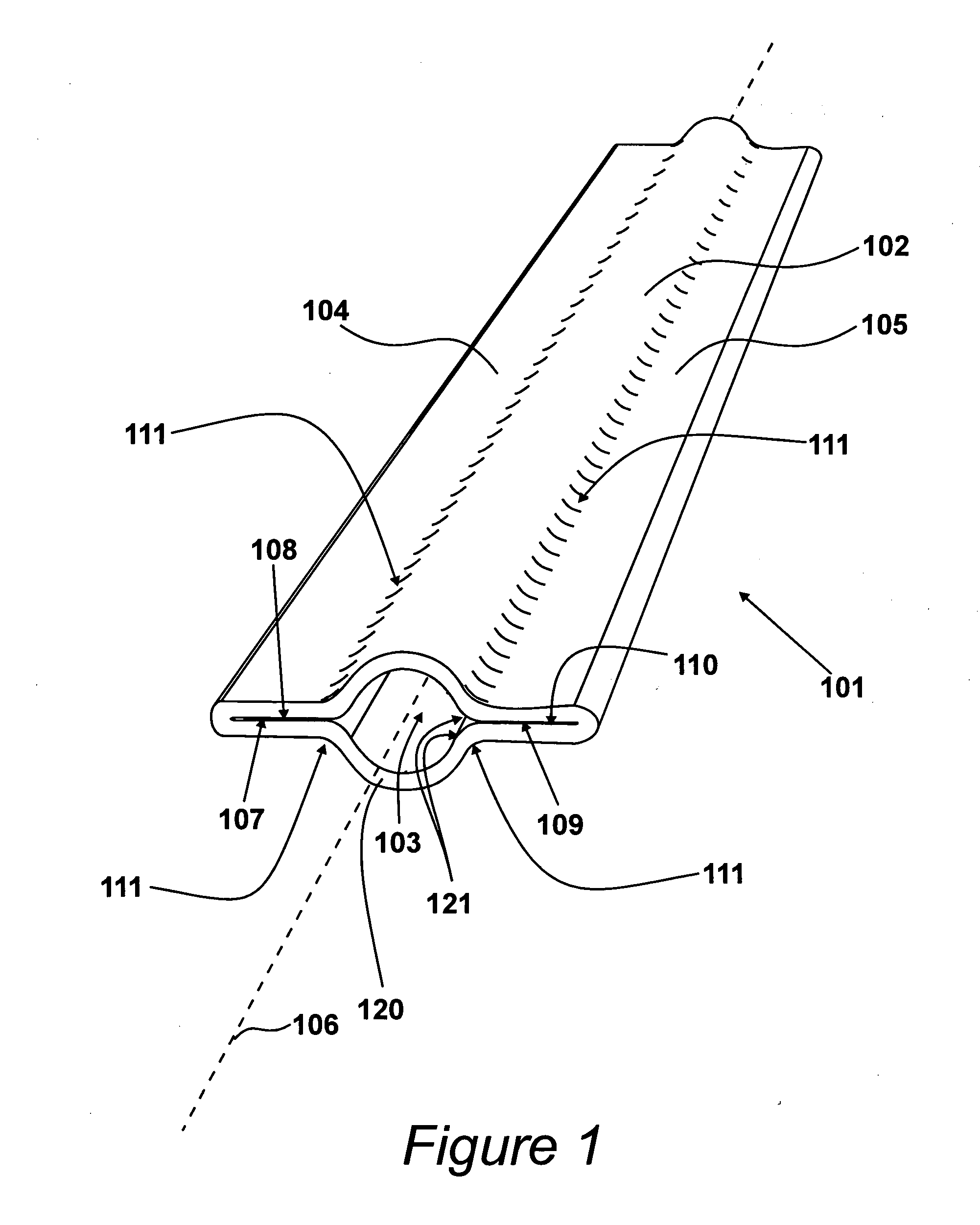
[0038]A heat transfer tube 101 embodying the present invention is shown in FIG. 1. The tube 101 has a central main flow portion 102 defining a main bore 103. A first wing-shaped protrusion 104 extends from one side of the main flow portion 102 and a second wing-shaped protrusion 105 extends from the opposite side of the main flow portion 102. Thus, the two wing-shaped protrusions 104 and 105 are symmetrically arranged around a centre line (or axis) 106 of the tube. As may be observed from FIG. 1, as well as extending away from the main flow portion 102, each of the wing-shaped protrusions extend axially along the tube 101. That is, they extend along the tube parallel to the axis 106.

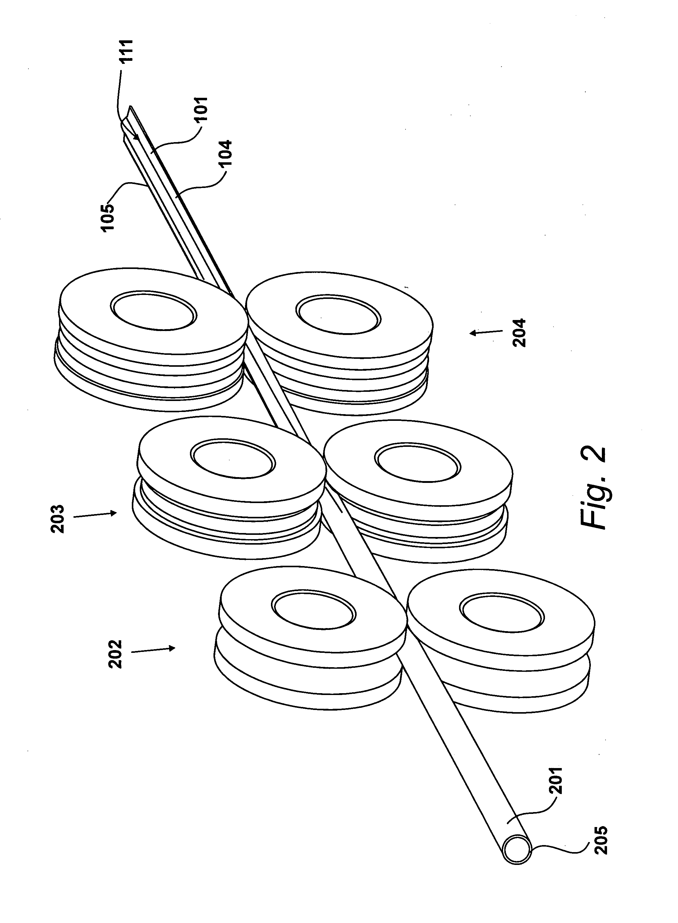
[0039]As will be explained in further detail below, the tube 101 is formed by deforming a length of cylindrical tubing. More specifically, the wall 120 of the tube is folded into the shape shown in FIG. 1. In the present case, the material of the tube has been deformed such that a portion 107 of th...


PUM

PropertyMeasurementUnit
Lengthaaaaaaaaaa
Shapeaaaaaaaaaa
Surface areaaaaaaaaaaa

Abstract

A heat transfer tube (101) for a heat exchanger. The wall (120) of the heat transfer tube comprising at least one axially extending wing-shaped protrusion (104, 105) to provide the tube with additional heat transfer surface area. The wing shaped protrusion is formed by a process comprising at least one of: (i) folding the wall of the tube; and (ii) extrusion.

Description

CROSS REFERENCE TO RELATED APPLICATIONS[0001]This application claims priority from German Gebrauchsmuster Application No. 20 2007 016 841.1, filed 30 Nov. 2007, the whole contents of which are incorporated herein by reference in their entirety.BACKGROUND OF THE INVENTION[0002]1. Field of the Invention[0003]The present invention relates to a heat transfer tube for a heat exchanger, a heat exchanger formed of the heat transfer tube and a method of manufacturing a heat transfer tube.[0004]2. Description of the Related Art[0005]Heat transfer tubes for evaporators or condensers of heating and cooling units are, for example, used for the evaporation and liquefaction of a cooling agent in refrigerators or air conditioners in vehicle engineering and also for general heat transfer. These heat transfer tubes consist, as generally known, of one tube with a smooth surface. In general a first fluid passes through the tube and heat is transferred through the walls of the tube between the fluid wi...

Claims


Application Information

Patent Timeline
IPC IPC(8): F28F1/16B23P15/26
CPCB21C37/155B21C37/225B21C37/26F28D1/0477F28D2021/007F28D2021/0071F28F1/06F28F1/16F28F1/26F28F1/36Y10T29/49377
Inventor KIRCHNER, JORGBALLI, CARLOCATALAN, IGNACIO
Owner BUNDY REFRIGERATION
Learn More