
Heat exchanger and method for manufacturing same

a technology of heat exchanger and heat exchanger, which is applied in the direction of indirect heat exchanger, lighting and heating apparatus, tubular elements, etc., can solve the problems of high manufacturing cost, complicated manufacturing process, and high labor intensity, and achieves low production cost, improved productivity, and reduced manufacturing costs

Inactive Publication Date: 2016-09-15
FLOWFORCE
View PDF27 Cites 0 Cited by
  • Summary
  • Abstract
  • Description
  • Claims
  • Application Information

AI Technical Summary

Benefits of technology

The present invention provides a way to make heat exchange apparatus more productive, reduce manufacturing costs, and improve their performance and durability. This is achieved by using a multiple-layer shell that can be easily molded and coated with synthetic resin, which makes it much more resistant to corrosion and pressure than conventional shells. Additionally, by eliminating or minimizing welding in the manufacturing process, defects such as deformation of tubes can be prevented, and the surface of the shell can be protected from excessive heat transfer. Overall, this innovation makes heat exchange apparatus more efficient, durable, and cost-effective.

Problems solved by technology

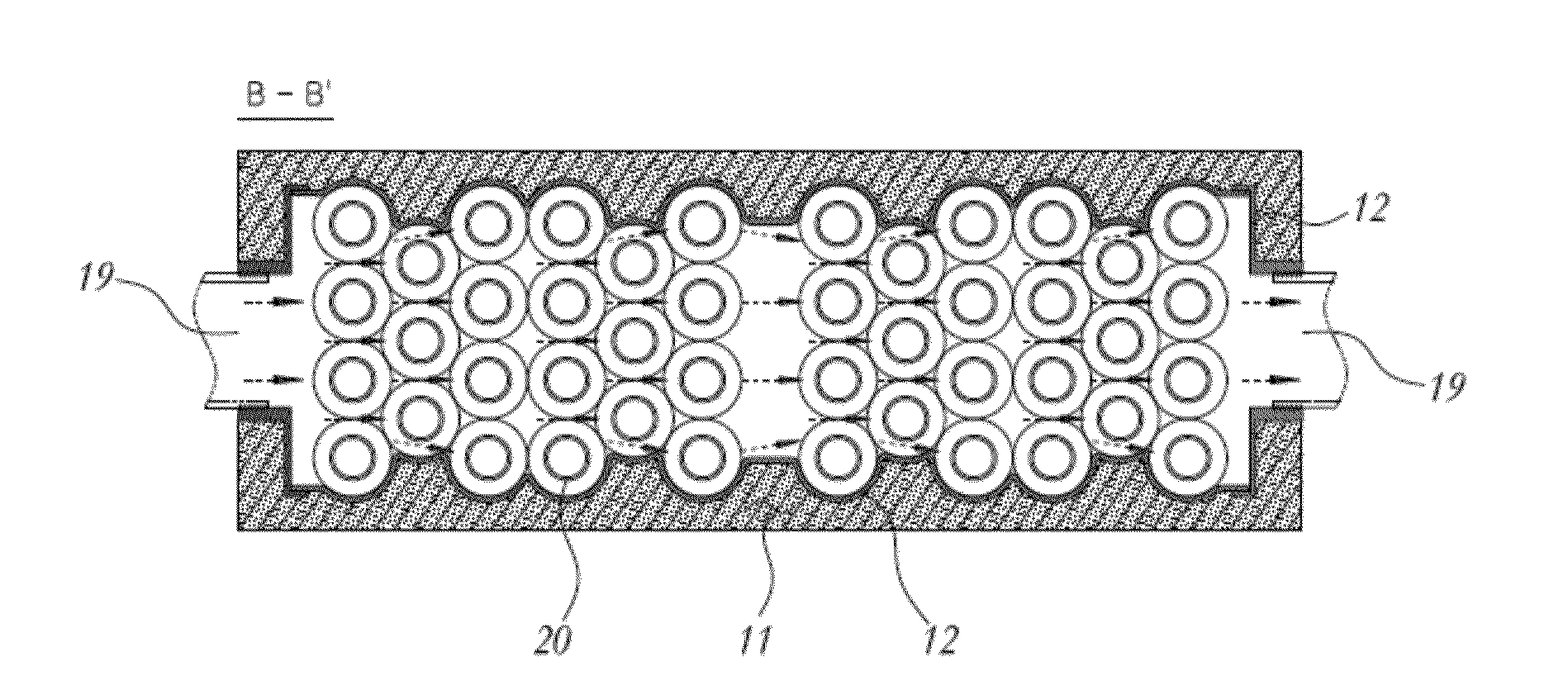
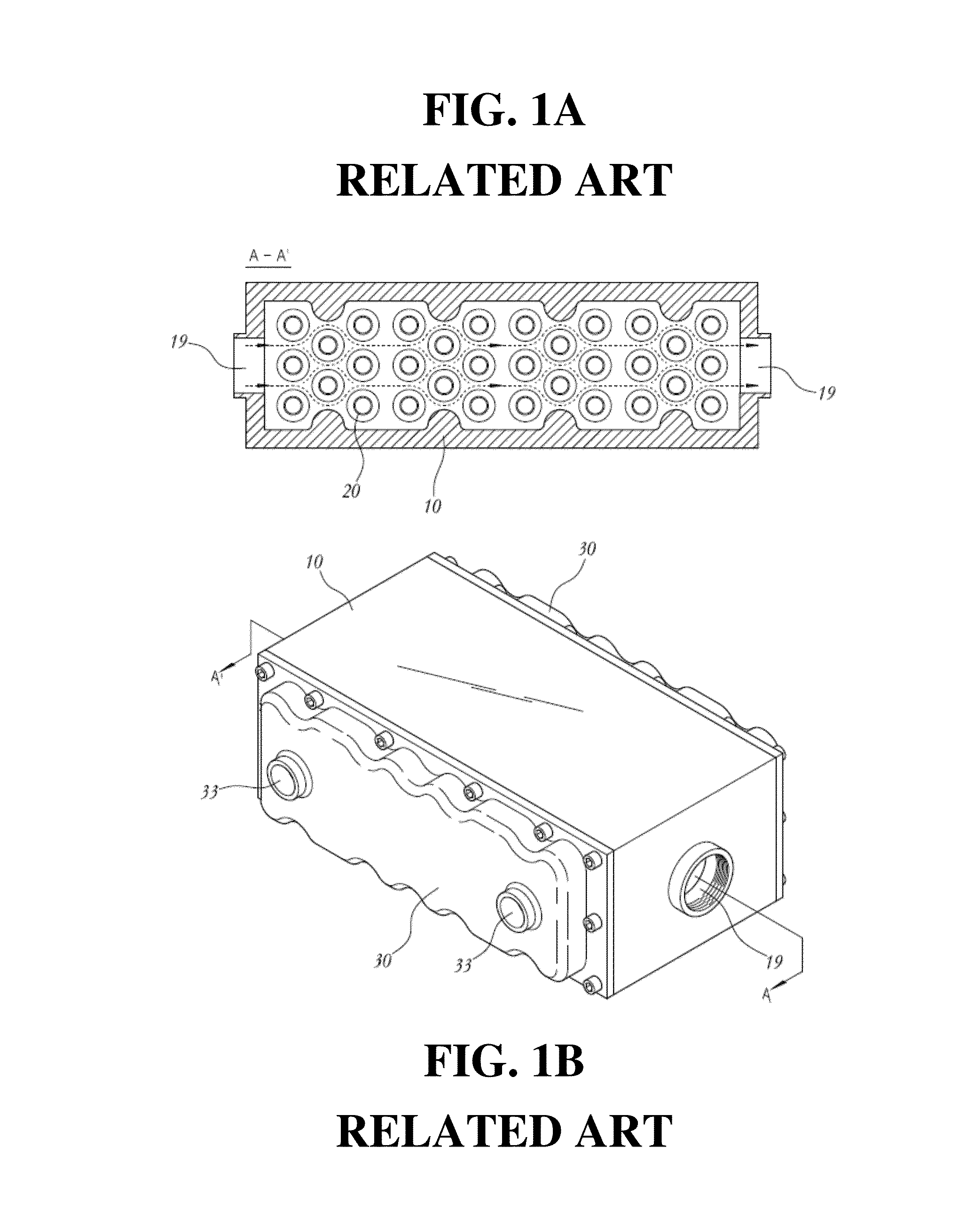
Accordingly, coupling the tubes 20 and welding the thick plates when the thick plates are assembled in the form of a box create a complicated manufacturing process and increase manufacturing cost.
Since, these processes are difficult to automate and require highly skilled manpower, there is a limit in mass-production of the shell 10 of the conventional heat exchange apparatus, and improvement of productivity and reduction of manufacturing cost through the mass-production are limited.
For example, deficiency in corrosion resistance of the shell 10 generates a problem in a heat exchange apparatus of an atomic power plant, a vessel or the like which uses sea water as a heat medium.

Method used


Image

  • Heat exchanger and method for manufacturing same
  • Heat exchanger and method for manufacturing same
  • Heat exchanger and method for manufacturing same

Examples


Embodiment Construction

[0027]Hereinafter reference will now be made in detail to various exemplary embodiments of the present invention, examples of which are illustrated in the accompanying drawings and described below. While the invention will be described in conjunction with exemplary embodiments, it will be understood that present description is not intended to limit the invention to those exemplary embodiments. On the contrary, the invention is intended to cover not only the exemplary embodiments, but also various alternatives, modifications, equivalents and other exemplary embodiments, which may be included within the spirit and scope of the invention as defined by the appended claims.

[0028]The terminology used herein is for the purpose of describing particular embodiments only and is not intended to be limiting of the invention. As used herein, the singular forms “a”, “an” and “the” are intended to include the plural forms as well, unless the context clearly indicates otherwise. It will be further ...


PUM

PropertyMeasurementUnit
structureaaaaaaaaaa
interior diameteraaaaaaaaaa
diameteraaaaaaaaaa

Abstract

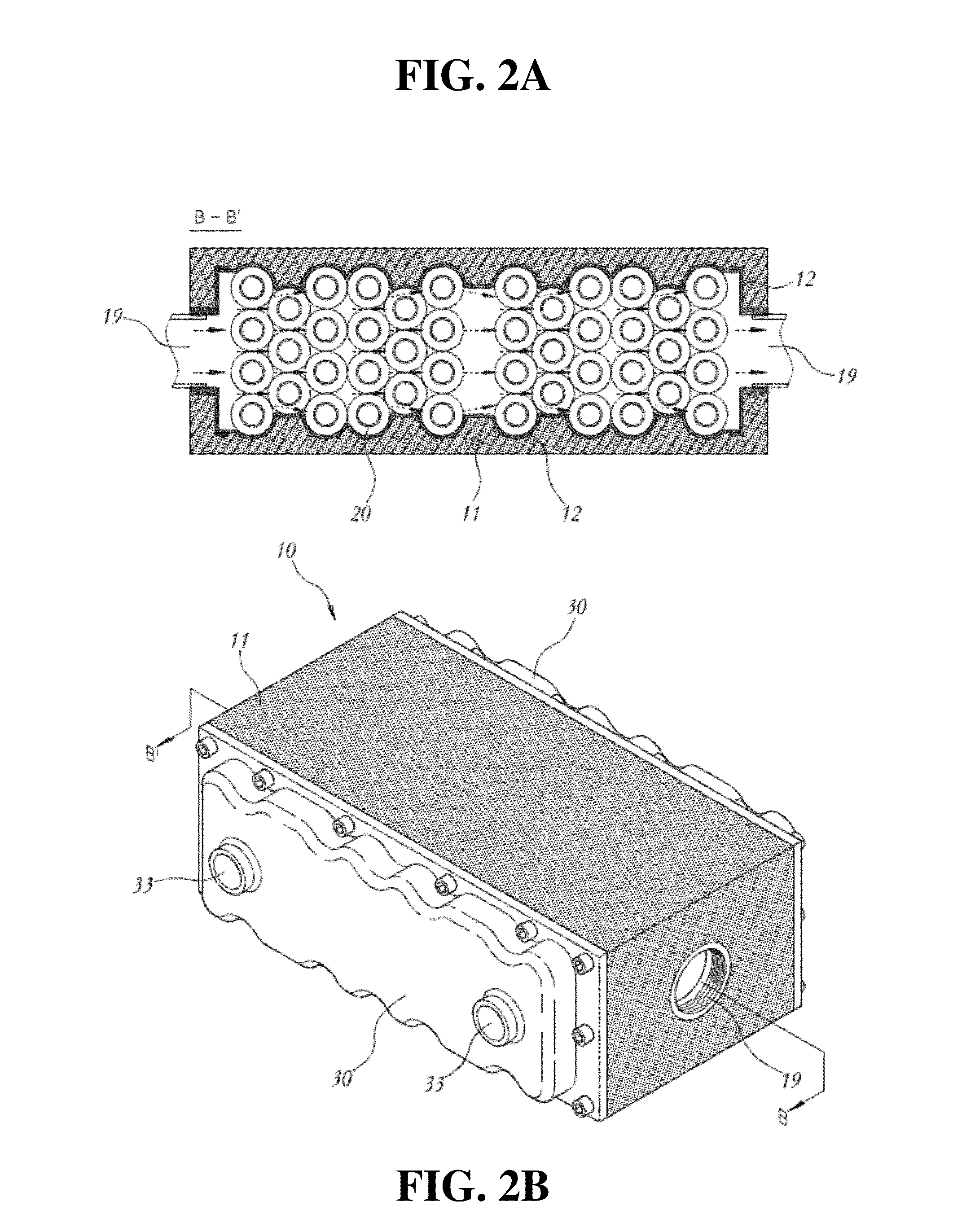
The present invention provides a heat exchange apparatus used as a cooling apparatus for hydraulic oil that operates a hydraulic machine. A heat exchange apparatus includes multiple embedded tubes through which a heat medium passes, are installed in the interior of a shell having thermal fluid, such as hydraulic oil, passing therethrough to allow a heat exchange between the heat medium and the thermal fluid. The shell of the heat exchange apparatus includes coupling the multiple tubes to closure thin plates that are a metal plate cut or bent in a predetermined shape, combining the closure thin plates in a box form, and forming a synthetic resin coating layer on the exterior surfaces of the closure thin plates. Thus, the heat exchange apparatus achieves productivity improvements and manufacturing cost reductions while ensuring performance including pressure resistance and air tightness, and durability.

Description

CROSS-REFERENCE TO RELATED APPLICATION[0001]This application is a continuation application of International Application No. PCT / KR2014 / 010422 filed on Nov. 3, 2014, which claims priority to Korean Application No. 10-2013-0146092 filed on Nov. 28, 2013. The applications are incorporated herein by reference.TECHNICAL FIELD[0002]The present invention relates to a heat exchange apparatus used as an apparatus for cooling down hydraulic oil for operating a hydraulic machine or the like and, more specifically, to a heat exchange apparatus having a plurality of tubes 20 embedded therein. The plurality of tubes 20 through which a heat medium such as a coolant passes is installed within a shell 10 through which a thermal fluid such as the hydraulic oil passes to provide heat exchange between the heat medium and the thermal fluid. The shell 10 of the heat exchange apparatus is formed by coupling the plurality of tubes 20 to closure thin plates 12, i.e., metal plates cut or bent in a predetermi...

Claims


Application Information

Patent Timeline
Patent Type & Authority Applications(United States)
IPC IPC(8): F28D7/00B23P15/26
CPCB23P15/26F28D7/0066F28D7/1623F28D2021/0049F28F9/00F28F9/0219F28F9/22F28F9/26F28F21/067F28D7/10F28F1/10
Inventor SEO, JUNG KOOK
Owner FLOWFORCE
Learn More