System and method for controlling a wind turbine

a wind turbine and control system technology, applied in the direction of mechanical equipment, electric generator control, machines/engines, etc., can solve the problems of difficult control of a wind turbine, adverse effects on generating potential at normal operating range, damage to electrical components, etc., to and reduce the rotational speed of one or more blades

Inactive Publication Date: 2010-12-16
REDRIVEN POWER
View PDF10 Cites 30 Cited by
  • Summary
  • Abstract
  • Description
  • Claims
  • Application Information

AI Technical Summary

Benefits of technology

[0017]In another aspect, the system further comprises a normally closed brake able to mechanically engage a generator shaft, whereby when power is not applied to the normally closed brake, the normally closed brake is in a closed position engaging the generator shaft to reduce the rotational speed of the one or more blades.
[0018]In another aspect, the system further comprises: a normally open yaw clutch mechanically connected between the yaw motor and the nacelle; the yaw clutch able to move to a closed position when power is applied to the yaw clutch and able to move to an open position in the absence of power; and, wherein, in the open position, the yaw moto

Problems solved by technology

However, if the blades spin too fast, damage may be caused to the electrical components because of an excessively high voltage or may occur to the structure of the turbine due to mechanical stress and vibrations.
On the other hand, if rotation of the blades is unduly restricted, by the imposition of a high electrical load for example, to accommodate anticipated extreme wind conditions, then the generating potential at normal operating ranges may be adversely affected.
The control of a wind turbine is particularly challenging due to the variability of the prime energy source, namely the wind, w

Method used


Image

  • System and method for controlling a wind turbine
  • System and method for controlling a wind turbine
  • System and method for controlling a wind turbine

Examples


Embodiment Construction

[0035]It will be appreciated that for simplicity and clarity of illustration, where considered appropriate, reference numerals may be repeated among the figures to indicate corresponding or analogous elements. In addition, numerous specific details are set forth in order to provide a thorough understanding of the embodiments described herein. However, it will be understood by those of ordinary skill in the art that the embodiments described herein may be practiced without these specific details. In other instances, well-known methods, procedures and components have not been described in detail so as not to obscure the embodiments described herein. Also, the description is not to be considered as limiting the scope of the embodiments described herein.

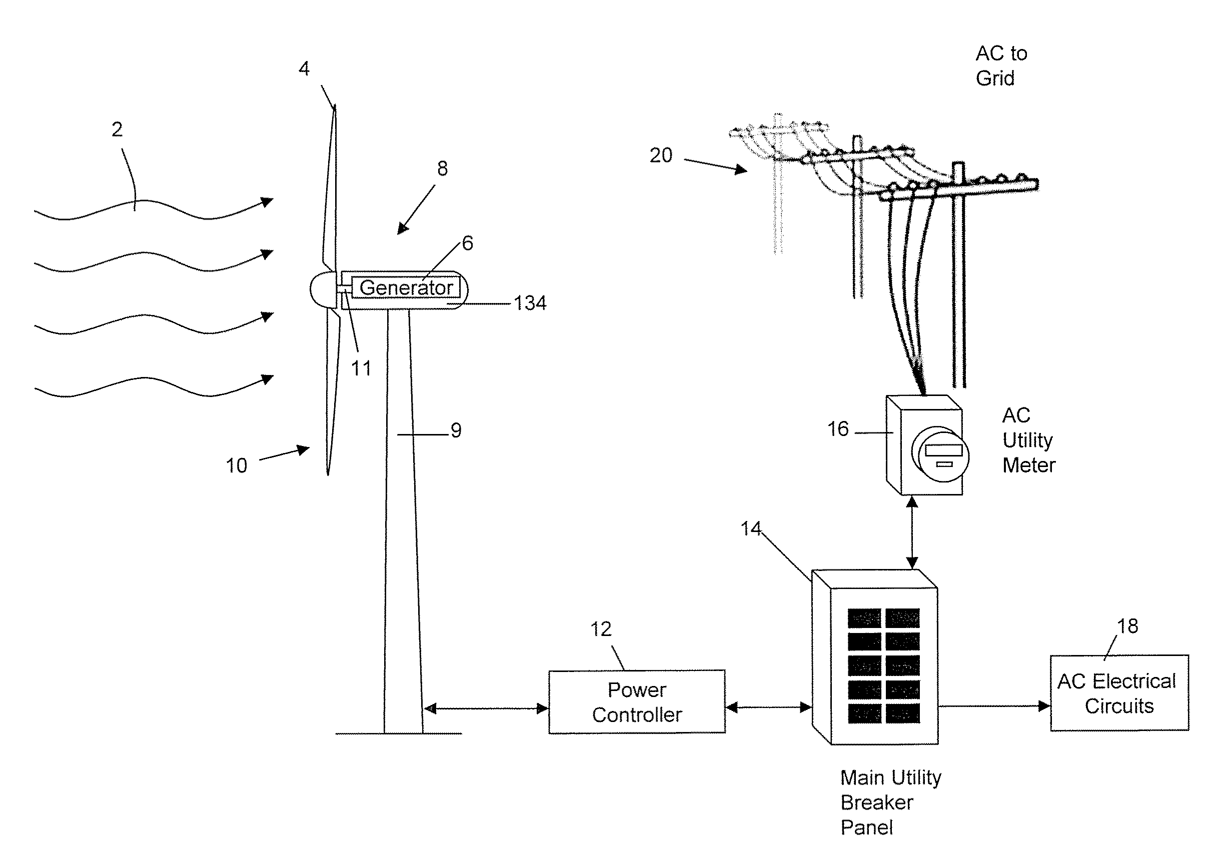
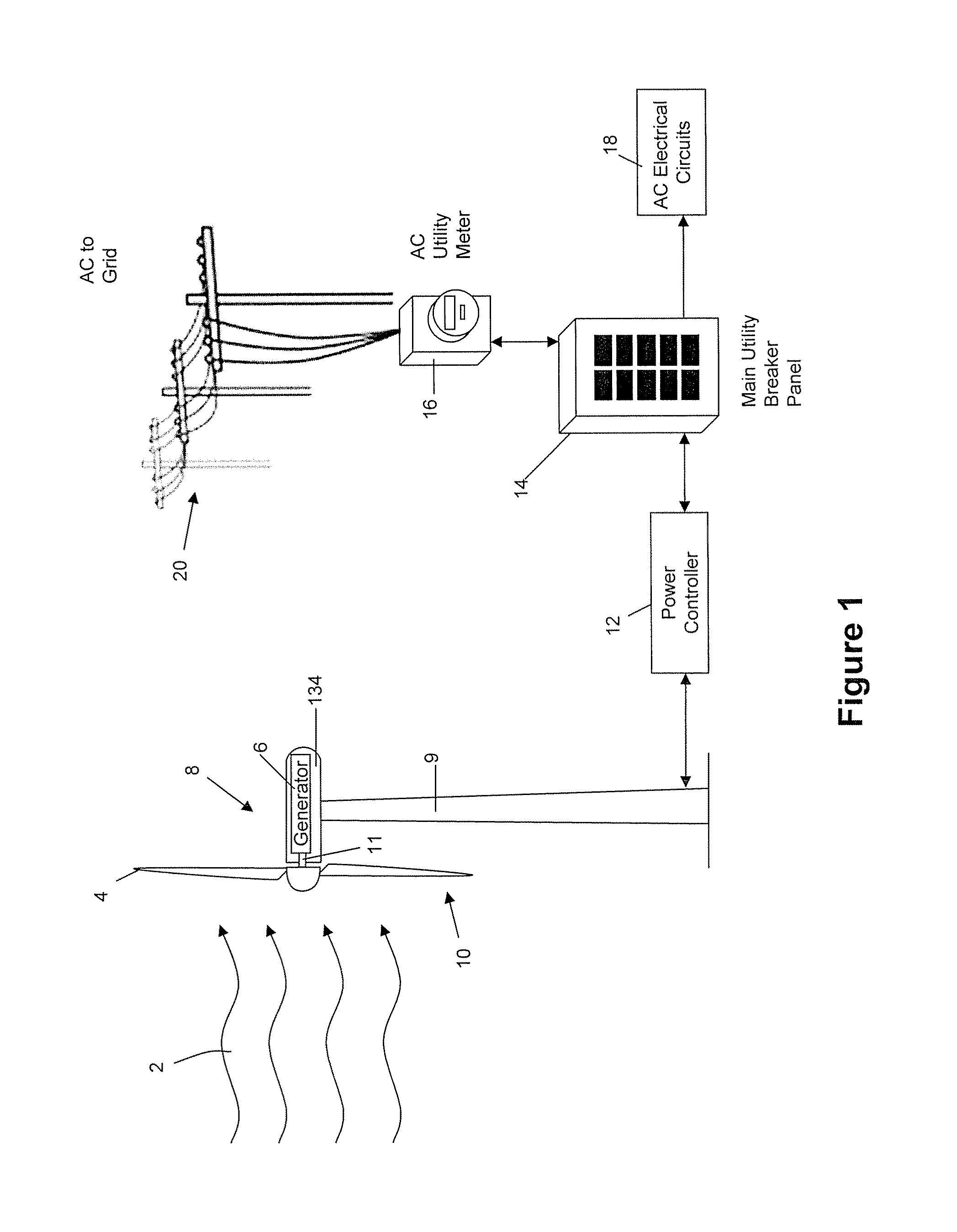
[0036]Referring therefore to FIG. 1, a wind turbine 8 is employed to supply electrical power to dedicated circuits 18, or, where surplus power is available, to an electrical grid 20. The wind turbine 8 is electrically connected to a powe...


PUM


Abstract

A system for controlling the RPM of a wind turbine comprising using inverters to draw current from the wind turbine, thereby slowing the rotational speed of the wind turbine blades. In another aspect, a resistor and a switching mechanism attached between the resistor and a phase line is provided to increase the load on the phase line. A yaw motor is also used to yaw the facing direction of the wind turbine out of the wind. Moreover, a normally closed switching mechanism can redirect current from a phase line through a resistor. A normally closed brake is also used to mechanically engage the turbine when the control system fails. A normally open yawing clutch when disengaged allows the nacelle of the wind turbine to rotate freely into the down wind direction. The system also comprises a switch that can create an electrical short between the phase lines of the turbine.

Description

CROSS REFERENCE TO RELATED APPLICATIONS[0001]This application claims priority from U.S. Provisional Application No. 61 / 178,692 filed on May 15, 2009; the contents of which are incorporated herein by reference.TECHNICAL FIELD[0002]The present invention relates to methods and apparatus for the control of a wind turbine.DESCRIPTION OF THE RELATED ART[0003]Electrical power can be generated by using wind to turn the blades of a wind turbine. The blades are connected to the rotor of an electrical generator that cooperates with a stator to generate an electrical current in a well known manner. The electrical power output of the turbine will vary depending on the speed of rotation of the blades. The faster the blades spin, the greater the voltage that can be generated and accordingly it is preferable to have the highest practical rotational speed. However, if the blades spin too fast, damage may be caused to the electrical components because of an excessively high voltage or may occur to th...

Claims


Application Information

Patent Timeline
IPC IPC(8): H02P9/04
CPCF03D7/0212F03D7/0272F03D7/0276F05B2270/1011F05B2270/107F05B2270/32F05B2270/321F05B2270/327F05B2270/329Y02E10/723Y02E10/72
Inventor GRANT, CHRISTOPHER BERNARD
Owner REDRIVEN POWER
Why Eureka
Try Eureka