
Method and apparatus for improved upstream frame synchronization in a passive optical network

Active Publication Date: 2010-12-16
ALCATEL LUCENT SAS
View PDF5 Cites 25 Cited by
  • Summary
  • Abstract
  • Description
  • Claims
  • Application Information

AI Technical Summary

Benefits of technology

[0009]In one aspect of the disclosure, there is provided a method for upstream transmission processing in a passive optical network. The method comprises generating a delimiter scheme that indicates one or more parameters of a second delimiter of a

Problems solved by technology

The high bit rates pose an increasing challenge for implementation of the burst-mode receiver, particularly of its analog circuits.
It can be difficult to design the TIA and LA that can restore the received signal fast enough and without distortion of its duty cycle, while supporting a wide dynamic range of the input signal.
As a result of higher signal distortion at the beginning of upstream frames, the probability of bit errors is typically higher than for other parts of upstream frames.
This issue is exacerbated at higher bit rates at which other causes of bit errors, like optical dispersion, are more pronounced.
The fact that the delimiter is located at the very beginning of the frame where signal distortion is most likely and that, unlike all other parts of the frame, it is not protected by forward error correction (FEC) error-control code, make the issue of its detection even more critical.
In a typical GPON deployment, the overall subscriber packet loss in the upstream traffic is dominated by the loss of frame reception due to failed delimiter detection, for example where the delimiter is too short, or where a detection algorithm either does not accept delimiters with errors or can only handle a limited number of errors.
This solution is inadequate because it is not immune to longer bursts of bit errors and because it can lead to false delimiter detection.

Method used


Image

  • Method and apparatus for improved upstream frame synchronization in a passive optical network
  • Method and apparatus for improved upstream frame synchronization in a passive optical network
  • Method and apparatus for improved upstream frame synchronization in a passive optical network

Examples


Embodiment Construction

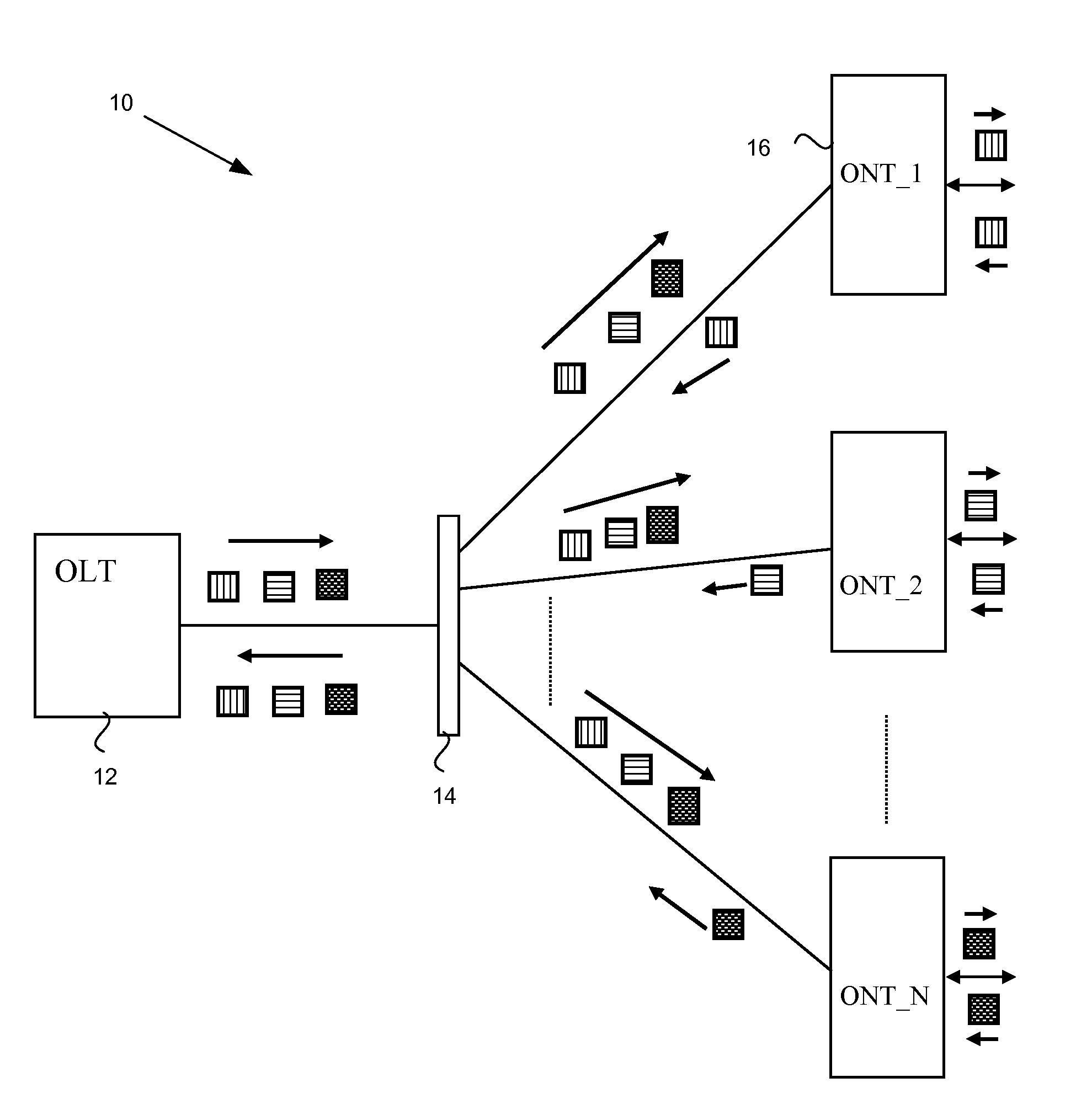
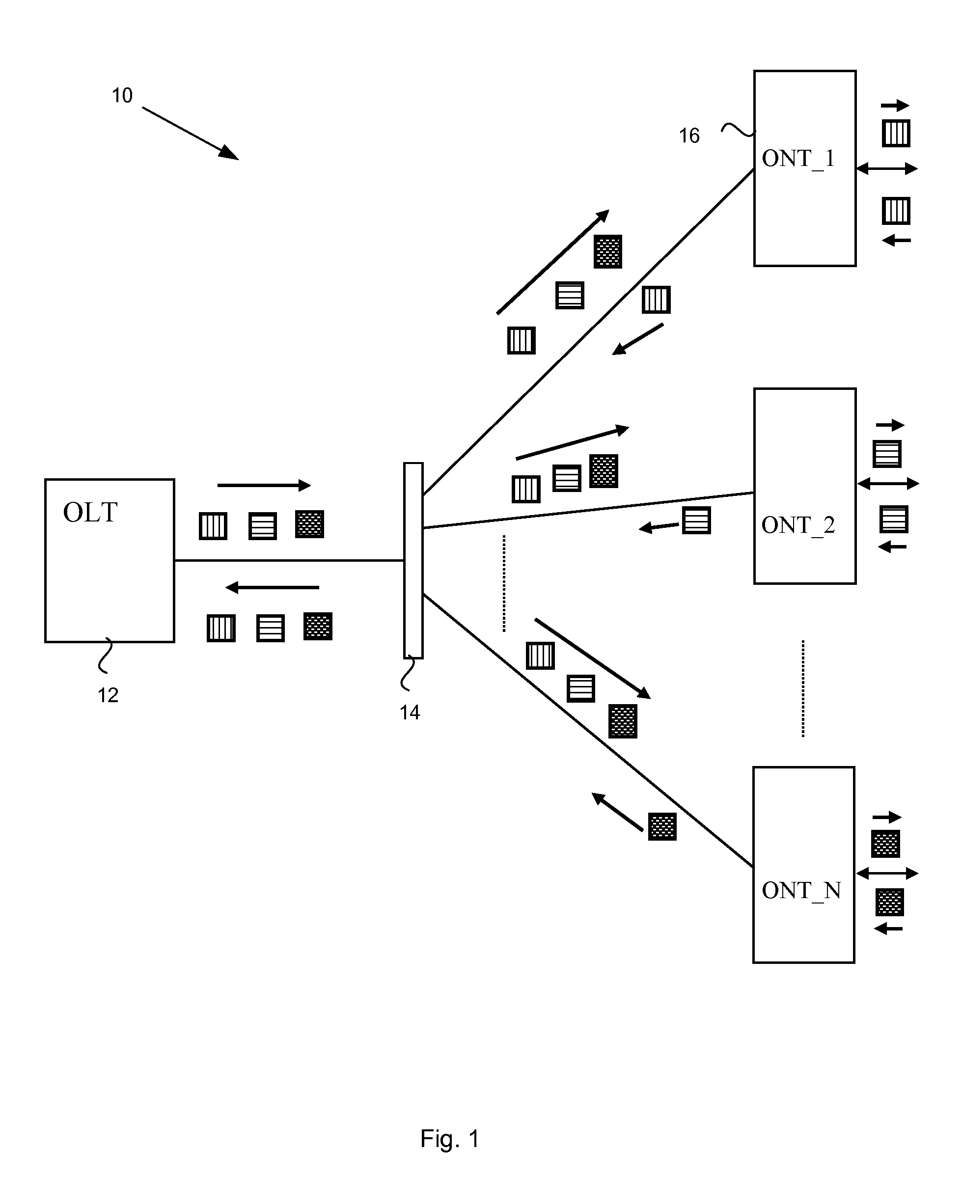
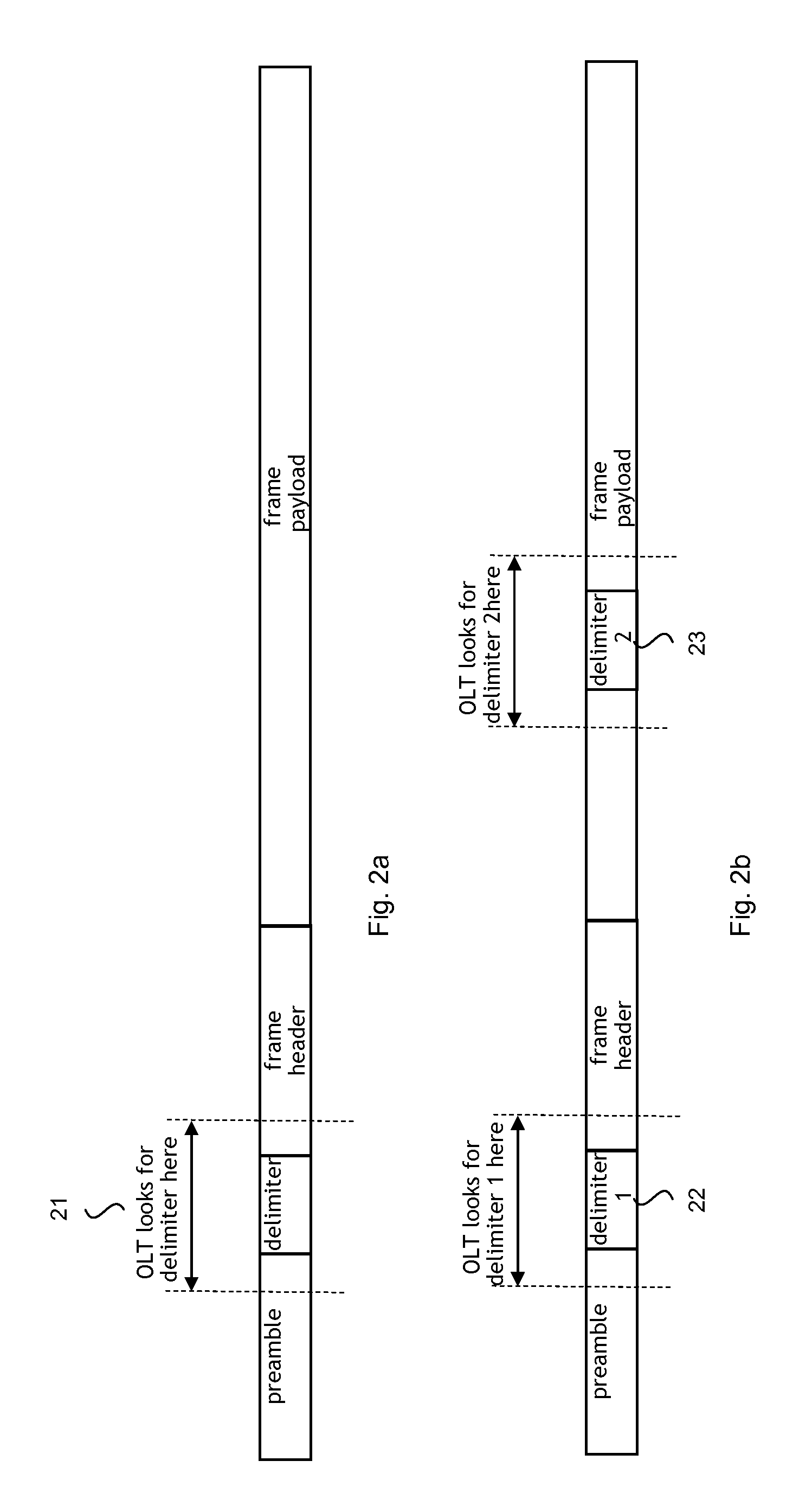
[0027]As shown in FIG. 1, PON upstream traffic originating from different ONUs 16 arrives at the OLT 12 in frames separated from each other in time. This separation is a result of scheduling and upstream bandwidth allocation performed by the OLT 12 and communicated to all ONUs 16. For well-designed ONUs 16 and OLTs 12, the worst-case difference between the expected and the actual arrival time of an upstream frame at the OLT is very small and typically does not exceed 1-2 byte periods. This feature allows the OLT 12 to look for the delimiter sequence only in a narrow time window 21, as illustrated in FIG. 2a. This feature is used in the present embodiments to detect additional delimiter sequences inserted at other known positions in the frame, with the same time resolution and without a risk of mistaking a payload bit sequence for the delimiter. Detection of multiple delimiters 22, 23 is illustrated in FIG. 2b.

[0028]A method for providing upstream communications in the PON 10 of FIG...


PUM


Abstract

In a passive optical network, upstream transmission frames from an ONU to an OLT can include additional delimiters that assist in overcoming high signal distortion at the beginning of the frame that can obscure an initial frame delimiter. The second delimiter can be inserted into the frame at various locations within the frame known to the OLT such that the OLT can active a delimiter detector at the beginning of a timing window for delimiter detection. The ONU can assist the OLT in synchronizing the frame by ensuring that a frame header immediately follows a second delimiter or appears at the start of a first FEC code block following the second delimiter. Depending on where the ONU inserts the second delimiter in the frame generation process, the second delimiter may be scrambled and / or may form part of the FEC.

Description

FIELD OF THE INVENTION[0001]This disclosure relates to a Passive Optical Network (PON) and to systems and methods for improving communications in a PON.BACKGROUND OF THE INVENTION[0002]A passive optical network (PON) is a flexible access network that is capable of providing a range of broadband and narrow-band services for business and residential customers. The underlying equipment is considered to be relatively inexpensive for network operators because they do not require any active equipment or power supplies between the operator's central office (CO) and customer's premises (CP). As shown in the PON 10 of FIG. 1, downstream PON traffic is destined from the Optical Line Termination (OLT) 12 residing in the CO towards a number of Optical Network Terminals (ONTs) 16 (or Optical Network Units (ONUs), not shown), residing in the CPs via an optical splitter 14.[0003]Since the OLT 12 is the only unit transmitting in the downstream direction, there can be no collision between downstream...

Claims


Application Information

Patent Timeline
IPC IPC(8): H04J14/00H03M13/05G06F11/10
CPCH04J3/1694H04L7/041H04Q11/0067H04Q2011/0079H04J3/0682H04L7/04H04J3/16
Inventor SUVAKOVIC, DUSAN
Owner ALCATEL LUCENT SAS
Features
  • Generate Ideas
  • Intellectual Property
  • Life Sciences
  • Materials
  • Tech Scout
  • Unparalleled Data Quality
  • Higher Quality Content
  • 60% Fewer Hallucinations
Learn More