
Proximal catheter flap for managing wire twist

a proximal catheter and wire twist technology, applied in the field of catheter and stent delivery and deployment assemblies, can solve the problems of affecting the repair of vessels that are diseased at the bifurcation, affecting the axial and overall structural strength of the catheter, so as to avoid structural distortion and increase the axial and overall structural strength. the effect of strength

Inactive Publication Date: 2010-12-16
ABBOTT CARDIOVASCULAR
View PDF90 Cites 3 Cited by
  • Summary
  • Abstract
  • Description
  • Claims
  • Application Information

AI Technical Summary

Benefits of technology

[0013]In various alternative embodiments, the stent delivery assembly may have an over lumen with a diameter large enough to enable passage of a second stent carried on a second catheter, and / or the over lumen has a diameter large enough to enable passage of a second stent carried on a second catheter. The stent delivery assembly may have an over lumen that has a diameter large enough to enable passage of a second stent carried on a second catheter. Also, the wall of the over lumen may be sufficiently rigid to maintain its shape, avoid structural distortion, and retain the side branch guide wire therein while the catheter is advanced to the bifurcation, and be sufficiently resilient to release the side branch guide wire as it is advanced into the side branch vessel. The over and under lumens may have varying wall thicknesses to control strength of the over lumen with a slit. Also, the catheter wall alongside the over lumen and under lumen may be thicker for increased axial and overall structural strength of the catheter.

Problems solved by technology

Repair of vessels that are diseased at a bifurcation is particularly challenging since the stent must be precisely positioned, provide adequate coverage of the lesion, provide access to any diseased area located distal to the bifurcation, and maintain vessel patency in order to allow adequate blood flow to reach the myocardium.
Where the stent provides coverage to the vessel at the diseased portion, yet extends into the vessel lumen at the bifurcation, the diseased area is repaired, but blood flow may be compromised in other portions of the bifurcation.
Unapposed stent elements may promote lumen compromise during neointimal formation and healing, producing restenosis and requiring further procedures.
Moreover, by extending into the vessel lumen at the bifurcation, the stent may block access to further interventional procedures.
Conventional stents are designed to repair areas of blood vessels that are removed from bifurcations, and, therefore are associated with a variety of problems when attempting to use them to treat lesions at a bifurcation.
The drawback with this approach is that there is no way to determine or guarantee that the main vessel stent struts are properly oriented with respect to the side branch or that an appropriate stent cell has been selected by the wire for dilatation.
The aperture created often does not provide a clear opening and creates a major distortion in the surrounding stent struts.
A further drawback with this approach is that there is no way to tell if the main-vessel stent struts have been properly oriented and spread apart to provide a clear opening for stenting the side branch vessel.
This technique also causes stent deformation to occur in the area adjacent to the carina, pulling the stent away from the vessel wall and partially obstructing flow in the originally non-jailed vessel.
Deforming the stent struts to regain access into the previously jailed strut is also a complicated and time consuming procedure associated with attendant risks to the patient and is typically performed only if considered an absolute necessity.
The risks of procedural complications during this subsequent deformation are considerably higher than stenting in normal vessels.
The inability to place a guide wire through the jailed lumen in a timely fashion could restrict blood supply and begin to precipitate symptoms of angina or even cardiac arrest.
In addition, platelet agitation and subsequent thrombus formation at the jailed site could further compromise blood flow into the side branch.
This procedure is also associated with the same issues and risks previously described when stenting only one vessel and deforming the struts through the jailed vessel.
In addition, since a conventional stent generally terminates at right angles to its longitudinal axis, the use of conventional stents to treat the origin of the previously jailed vessel (typically the side branch vessel) may result in blocking blood flow of the originally non-jailed vessel (typically the parent vessel) or failure to provide adequate coverage of the diseased area in the previously jailed vessel (typically a side branch vessel).
Such a position of the stent results in a bifurcation treatment that does not provide full coverage or has a gap on the proximal side (the origin of the side branch) of the vessel.
One of the drawbacks of this approach is that the orientation of the stent elements protruding from the side branch vessel into the main vessel is completely random.
In addition excessive metal coverage exists from overlapping strut elements in the parent vessel proximal to the carina area.
When dilating the main vessel the stent struts are randomly stretched, thereby leaving the possibility of restricted access, incomplete lumen dilatation, and major stent distortion.
The foregoing stent deployment assemblies may encounter some problems and limitations.
Typically, there is uncovered intimal surface segments on the main vessel and side branch vessels between the stented segments or there is excessive coverage in the parent vessel proximal to the bifurcation.
An uncovered flap or fold in the intima or plaque will invite a “snowplow” effect, representing a substantial risk for sub acute thrombosis, and the increased risk of the development of restenosis.
Further, where portions of the stent are left unapposed within the lumen, the risk for subacute thrombosis or the development of restenosis is increased.
These stents and delivery assemblies for treating bifurcations are sometimes difficult to use and deliver.
Further, even where placement has been successful, the side branch vessel can be “jailed” or covered so that there is impaired access to the stented area for subsequent intervention.
There is sometimes difficulty in treating a diseased bifurcation confined to a vessel segment but extending very close to a distal branch point which is not diseased and does not require treatment.

Method used


Image

  • Proximal catheter flap for managing wire twist
  • Proximal catheter flap for managing wire twist
  • Proximal catheter flap for managing wire twist

Examples


Embodiment Construction

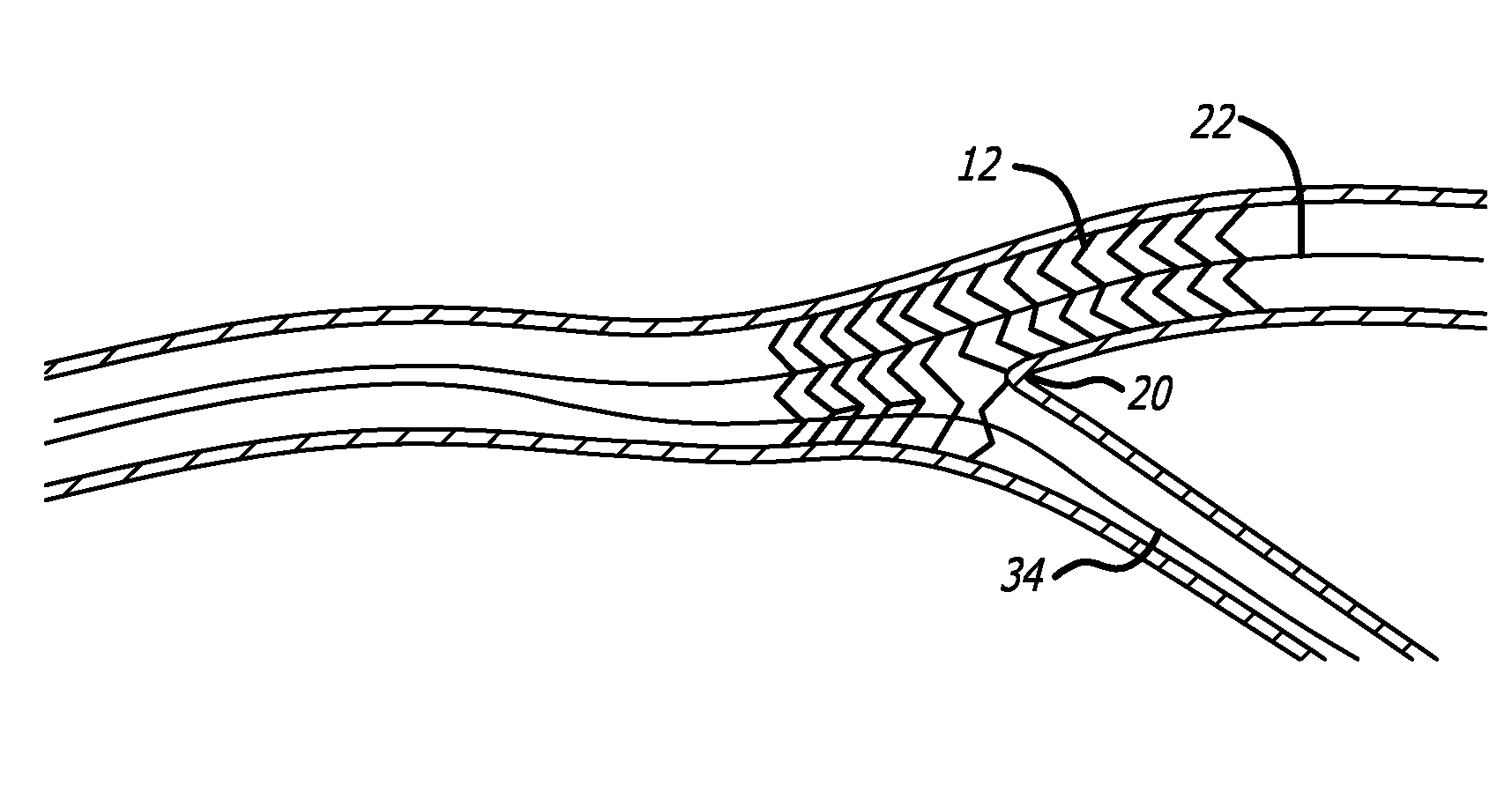
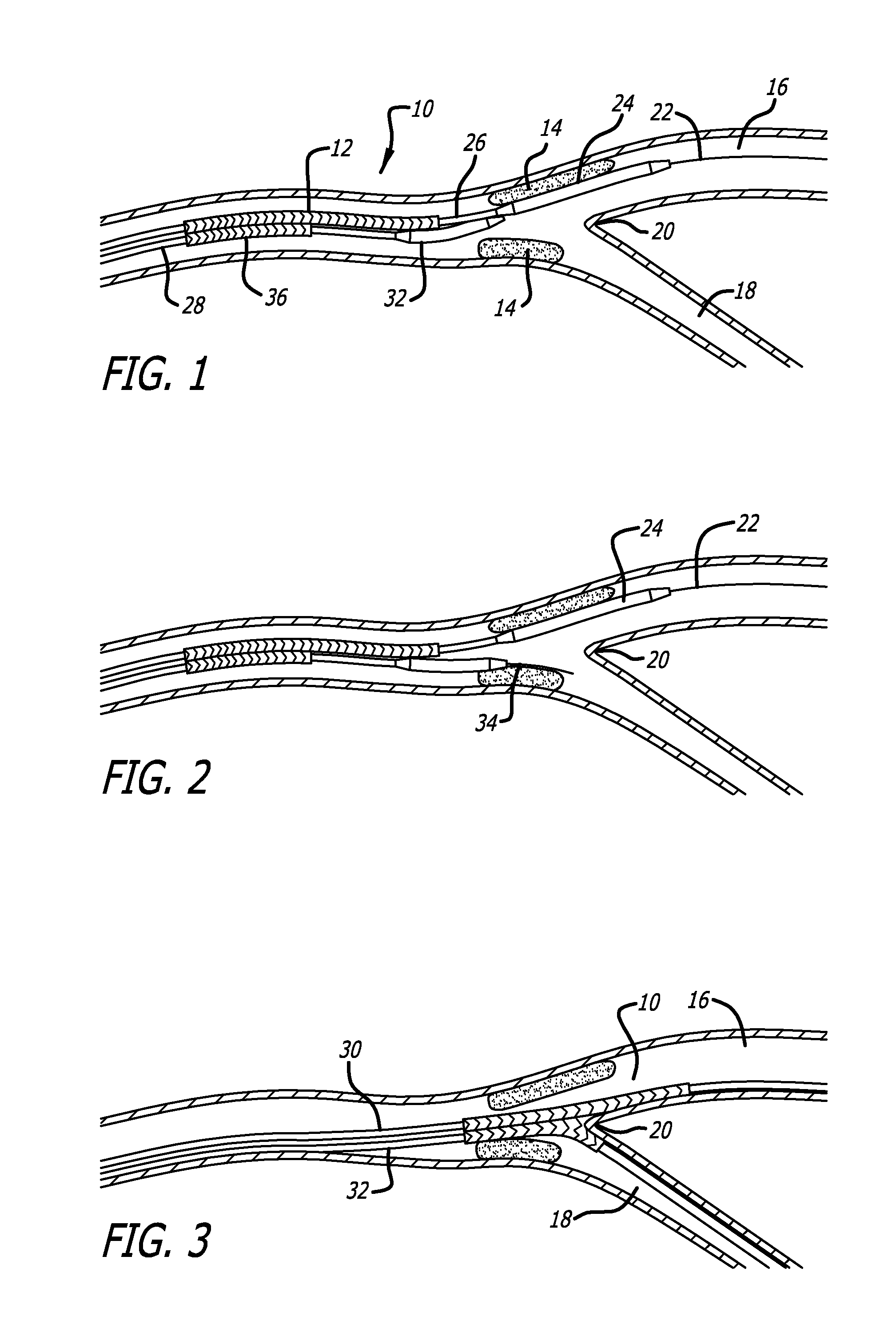
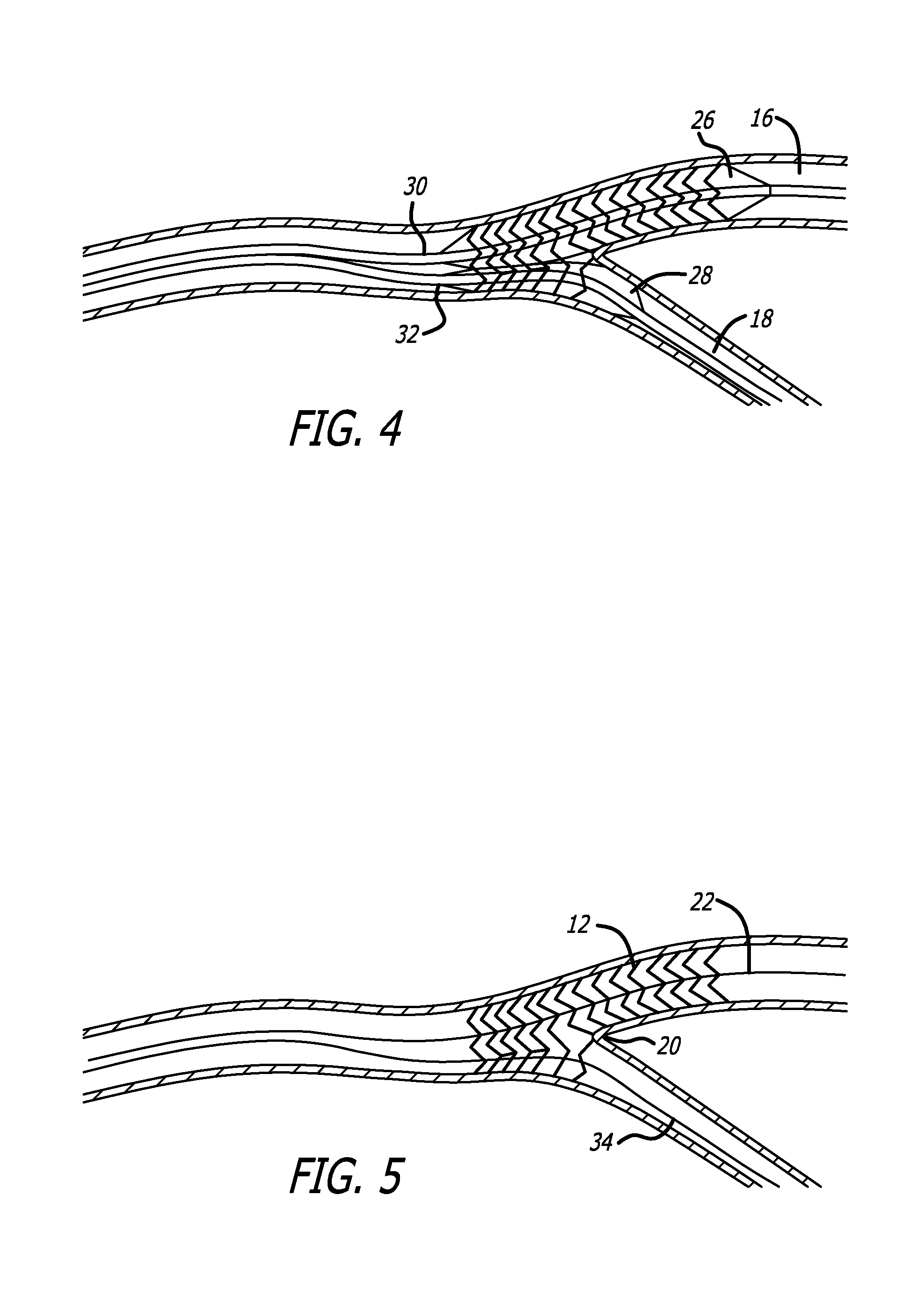
[0020]The present invention is directed to a catheter system for treating bifurcation lesions. FIG. 1 is a schematic depiction of a preferred embodiment bifurcated stent delivery system 10 advanced into a patient's bifurcated blood vessel having a main branch vessel 16 and a side branch vessel 18. The bifurcated system 10 is used for treatment of plaque 14 located at the bifurcation. The system 10 includes a dual lumen catheter 30, 32 carrying a specially designed bifurcated stent 12 thereon and having one catheter branch 30 extending the entire length of the stent 12 and another catheter branch 32 passing through a port 36 in the stent 12. The pair of catheter branches 30, 32 at the distal ends are held together by an optional joining mandrel 24 and wherein the main branch guide wire 22 extends into the main branch 16. Each branch of the catheter 30, 32 includes a respective expandable member or balloon 26, 28. The side branch balloon 28 exits the stent 12 at about the midpoint of ...


PUM


Abstract

A stent delivery system for treating a diseased bifurcation vessel having a catheter with a securement feature. The delivery system includes a dual lumen catheter with one or more balloons and a specialized stent having a side port mounted on the balloon. The securement feature is a flap that retains a side branch guide wire near the catheter body and wherein the distal tip of the guide wire is positioned near the side port of the stent. At the bifurcation, the side branch guide wire is freed from the flap to advance into the side branch vessel through the stent side port.

Description

FIELD OF THE INVENTION[0001]The invention relates to a method and apparatus for delivery and implantation of stents. More particularly, the invention relates to a catheter and stent delivery and deployment assemblies for use in repairing bifurcations and blood vessels that are diseased.BACKGROUND OF THE INVENTION[0002]Stents conventionally repair blood vessels that are diseased. Stents are generally hollow and cylindrical in shape and have terminal ends that are generally perpendicular to their longitudinal axis. In use, the conventional stent is positioned at the diseased area of a vessel and, after deployment, the stent provides an unobstructed pathway for blood flow.[0003]Repair of vessels that are diseased at a bifurcation is particularly challenging since the stent must be precisely positioned, provide adequate coverage of the lesion, provide access to any diseased area located distal to the bifurcation, and maintain vessel patency in order to allow adequate blood flow to reach...

Claims


Application Information

Patent Timeline
Patent Type & Authority Applications(United States)
IPC IPC(8): A61F2/06
CPCA61F2/954A61F2/958A61F2250/0039A61F2002/065A61F2002/061
Inventor NEWHAUSER, RICHARD
Owner ABBOTT CARDIOVASCULAR
Features
  • Generate Ideas
  • Intellectual Property
  • Life Sciences
  • Materials
  • Tech Scout
  • Unparalleled Data Quality
  • Higher Quality Content
  • 60% Fewer Hallucinations
Learn More