Method for controlling the compressed air supply of an internal combusion engine and transmission

Inactive Publication Date: 2010-12-16
ZF FRIEDRICHSHAFEN AG
View PDF31 Cites 35 Cited by
  • Summary
  • Abstract
  • Description
  • Claims
  • Application Information

AI Technical Summary

Benefits of technology

[0026]It is also considered as an advantage, when it is provided, that the transmission control device, during a gear ratio change, commands the control device for the control of the mechanism for the injection of additional compressed air in a way and in consideration of the dynamic behavior of this compressed air injection mechanism and the combustion engine, that this combustion engine, after the gear ratio change, provides the m

Problems solved by technology

Since the turbo chargers with variable geometry are comparatively expensive to manufacture and can only be driven through complex control and monitoring methods, the motor

Method used


Image

  • Method for controlling the compressed air supply of an internal combusion engine and transmission
  • Method for controlling the compressed air supply of an internal combusion engine and transmission

Examples


Embodiment Construction

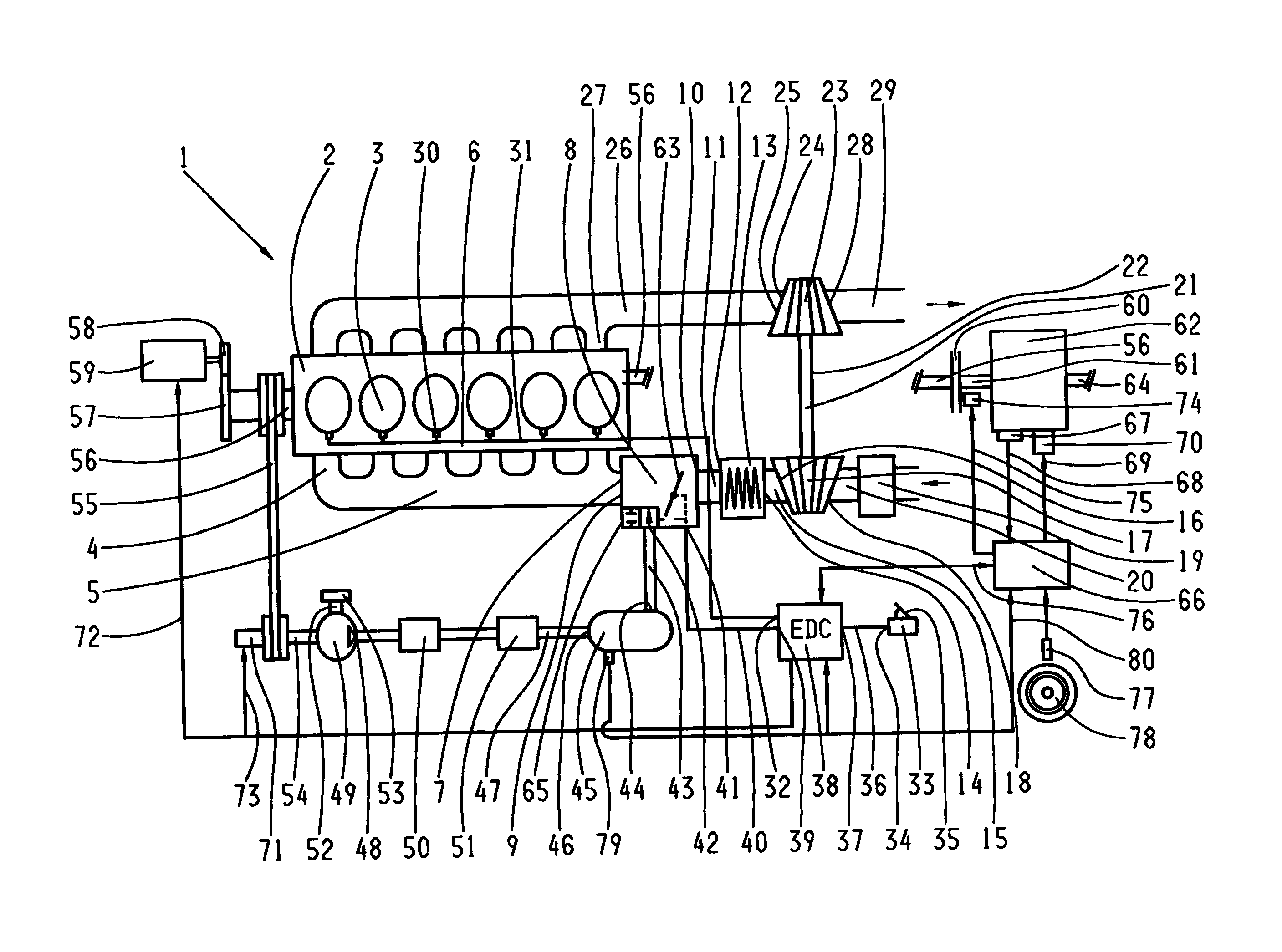
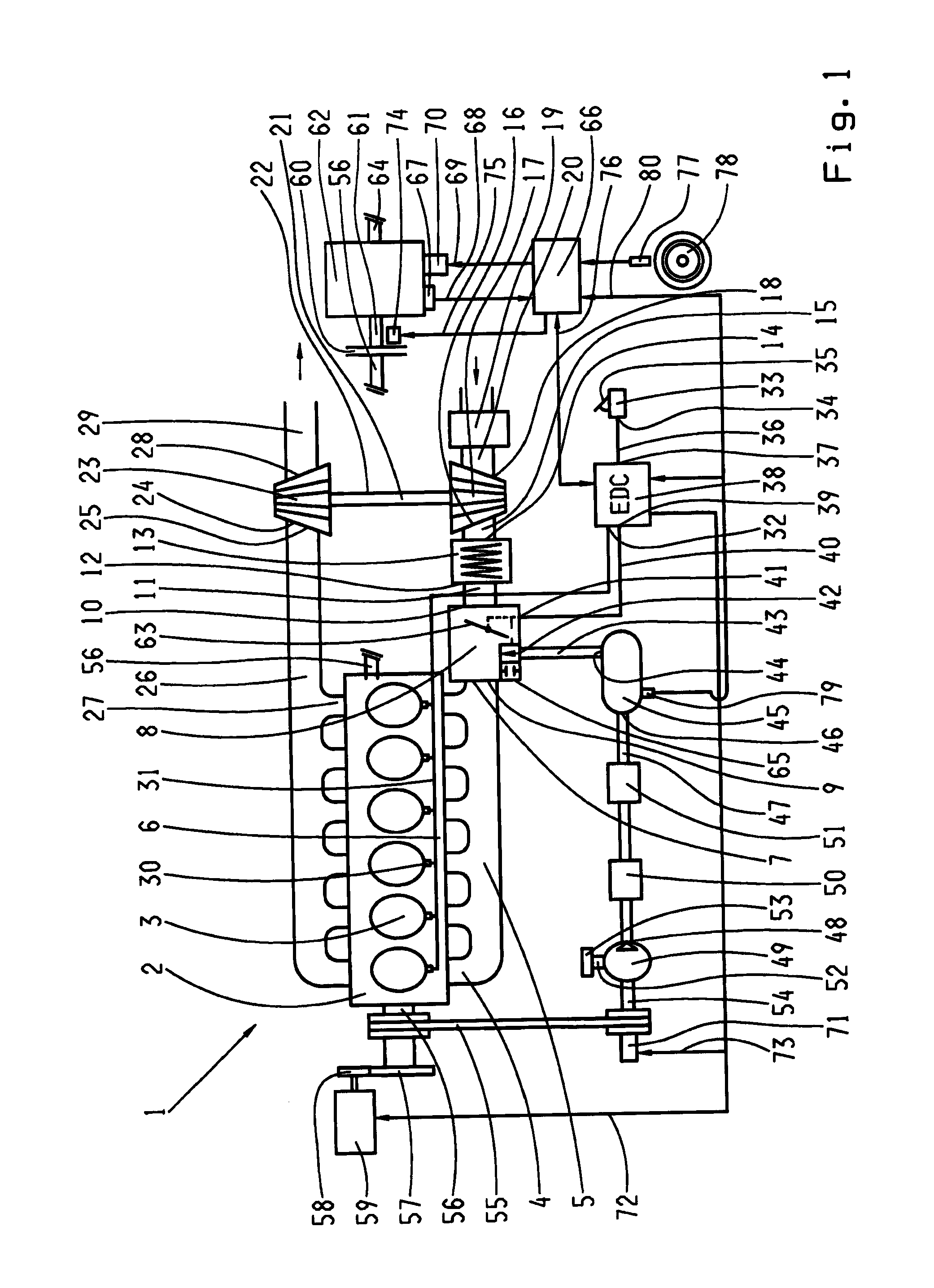
[0034]Belonging to the drive train 1 is a diesel engine 2 with six cylinders 3 lined up in a row of the cylinder block 6 and equipped with a turbo compressor 17. The intake lines 4 of the cylinders 3 are connected to a manifold 5 which has a connection flange 7, to which an air intake system 8 with its second end flange 9 is connected for the outflow of air. The first end flange 10, for the intake of air, is coupled via a pipe 11 with the outflow opening 12 of an intercooler 13, where its intake opening 14 is coupled via a pipe 15 with the outflow opening 16 of the turbo compressor 17. Connected to the intake opening 18 of the turbo compressor 17 is an air filter 19 with a pipe 20. The turbo compressor 17 forms a part of the turbo charger 22, where its exhaust turbine 23 with its intake opening 24 is connected to the outflow opening 25 of the exhaust manifold 26. The turbo compressor 17 and the exhaust turbine 23 are attached to a pivoted shaft 21. The cylinders 3 are connected via ...


PUM


Abstract

A method to operate a vehicle drive train comprising a combustion engine, a turbo charger assigned to the combustion engine, a mechanism for injecting additional compressed air into an air intake system of the combustion engine and a transmission. The method enables practical use of a compressed air injection mechanism, in the drive train, and comprises the step of controlling the time, the duration, the pressure and/or the volume of the additional compressed air, to be injected into the air intake system of the combustion engine, depending upon the performance request of the driver, the actual rotational speed and load condition of the combustion engine, the speed of the vehicle, and the procedures of the gear ratio change of the transmission.

Description

[0001]This application is a National Stage completion of PCT / EP2009 / 050822 filed Jan. 26, 2009, which claims priority from German patent application Ser. No. 10 2008 000 324.7 filed Feb. 18, 2008.FIELD OF THE INVENTION[0002]The invention concerns a method to operate a vehicle drive train with a combustion engine, a turbo charger assigned to this combustion engine, a mechanism to inject additional compressed air into an air intake tract of the combustion engine, and a transmission.BACKGROUND OF THE INVENTION[0003]It is known, for instance, through the patent applications WO 2006 / 037564 A1, WO 2006 / 089779 A1, and WO 2006 / 089780 A1 that a piston combustion engine, equipped with a turbo charger, generates at lower rotational speeds comparatively low torques, because the amount of air delivered, by a conventional turbocharger for a torque increase, into the intake tract of the motor depends, as determined by the system, on the particular exhaust flow of the combustion engine which drives...

Claims


Application Information

Patent Timeline
IPC IPC(8): B60W10/10F02D23/00B60W10/06
CPCB60W10/06B60Y2400/435F02B33/44F02B37/04F02B37/12F02D41/0007F02D41/0225F02D41/023F02D2200/501F02D2200/602F16H59/74F16H61/0213F16H63/50Y02T10/144B60W50/06Y02T10/12
Inventor JAGER, THOMASRUCHARDT, CHRISTOPHMAIR, ROLAND
Owner ZF FRIEDRICHSHAFEN AG
Why Eureka
Try Eureka