
Oxidation catalyst fault diagnosis unit and oxidation catalyst fault diagnosis method and internal combustion engine exhaust purification apparatus

Inactive Publication Date: 2010-12-23
BOSCH CORP
View PDF1 Cites 38 Cited by
  • Summary
  • Abstract
  • Description
  • Claims
  • Application Information

AI Technical Summary

Benefits of technology

[0017]According to the oxidation catalyst fault diagnosis unit and the oxidation catalyst fault diagnosis method of the present invention, focusing on the characteristic that a NOx sensor also reacts to ammonia, the reducing agent is delivered such that a predetermined quantity of the ammonia flows out to the downstream side of the reduction catalyst, the ratio of ammonia oxidized by the oxidation catalyst placed on the downstream side of the reduction catalyst is calculated, and fault diagnosis of the oxidation catalyst is performed, so fault diagnosis of the oxidation catalyst is performed with good precision in a desired time period regardless of the operating state of the internal combustion engine. Further, determination of whether or not the oxidation catalyst is faulty is performed on the basis of the oxidation efficiency of the oxidation catalyst, so determination of whether or not the oxidation catalyst is faulty is performed with good precision even under various operating conditions. Consequently, there are provided an oxidation catalyst fault diagnosis unit and an oxidation catalyst fault diagnosis method where there are fewer constraints on the time period of diagnosis and where fault diagnosis of the oxidation catalyst is performed with good precision.
[0018]Further, according to the internal combustion engine exhaust purification apparatus of the present invention, the exhaust purification apparatus is equipped with the fault diagnosis unit where fault diagnosis of the oxidation catalyst is performed in a desired time period regardless of the operating state and operating conditions of the internal combustion engine, so there is provided an exhaust purification apparatus where the ammonia is efficiently oxidized by the oxidation catalyst and release of the ammonia into the atmosphere is prevented even when the ammonia flows out to the downstream side of the reduction catalyst.

Problems solved by technology

However, sometimes some of the generated ammonia flows out to the downstream side of the selective reduction catalyst due to error in the dosage of the reducing agent instructed by a control unit or degradation of the SCR system over time.
But sometimes the efficiency of the oxidation catalyst drops because of faults including thermal degradation, degradation over time, and cracks.
When a fault arises in the oxidation catalyst, the oxidation catalyst cannot sufficiently oxidize and break down the ammonia flowing out to the downstream side of the selective reduction catalyst, and there is the potential for the ammonia to be released into the atmosphere.

Method used


Image

  • Oxidation catalyst fault diagnosis unit and oxidation catalyst fault diagnosis method and internal combustion engine exhaust purification apparatus
  • Oxidation catalyst fault diagnosis unit and oxidation catalyst fault diagnosis method and internal combustion engine exhaust purification apparatus
  • Oxidation catalyst fault diagnosis unit and oxidation catalyst fault diagnosis method and internal combustion engine exhaust purification apparatus

Examples


first embodiment

1. Exhaust Purification Apparatus

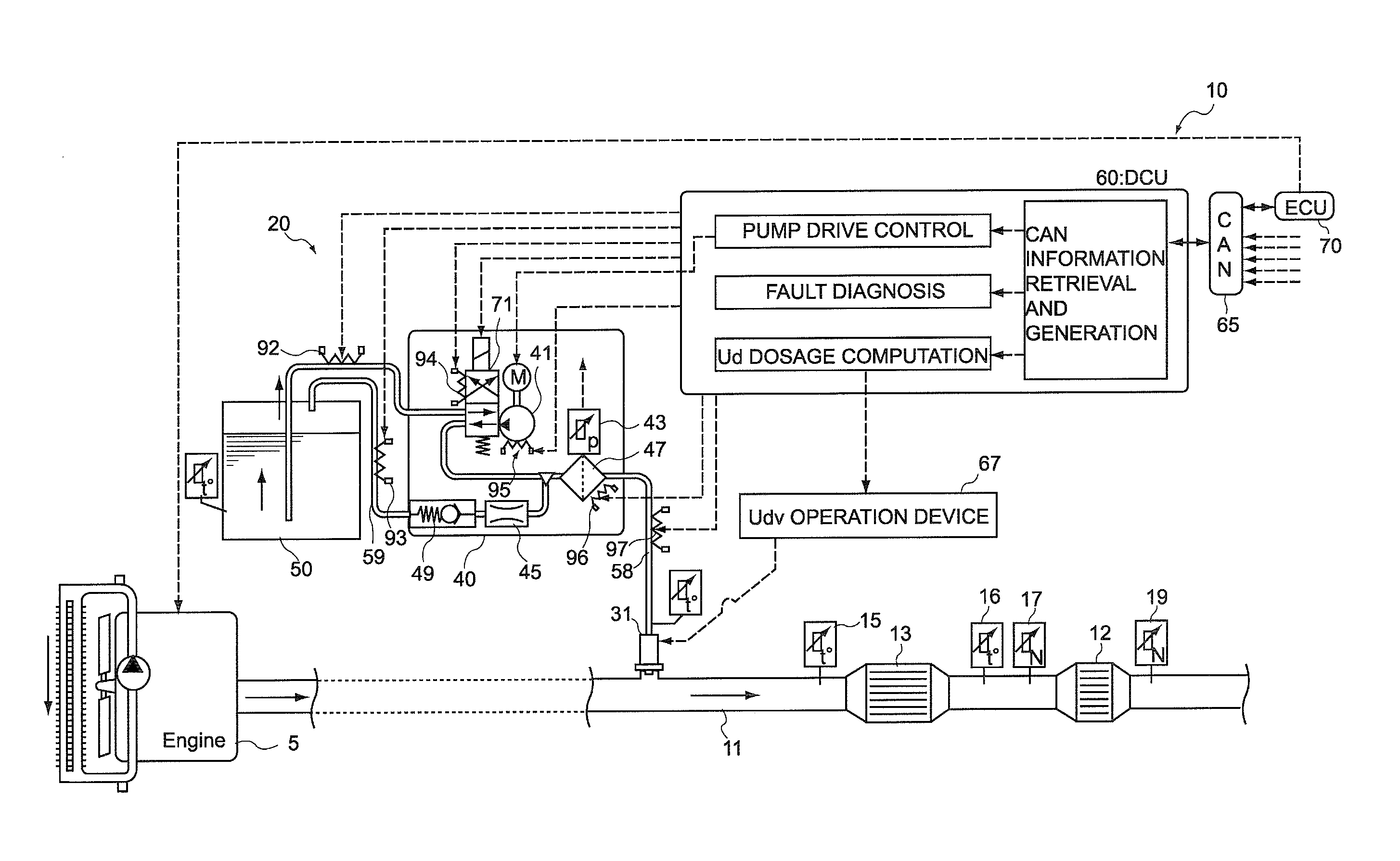
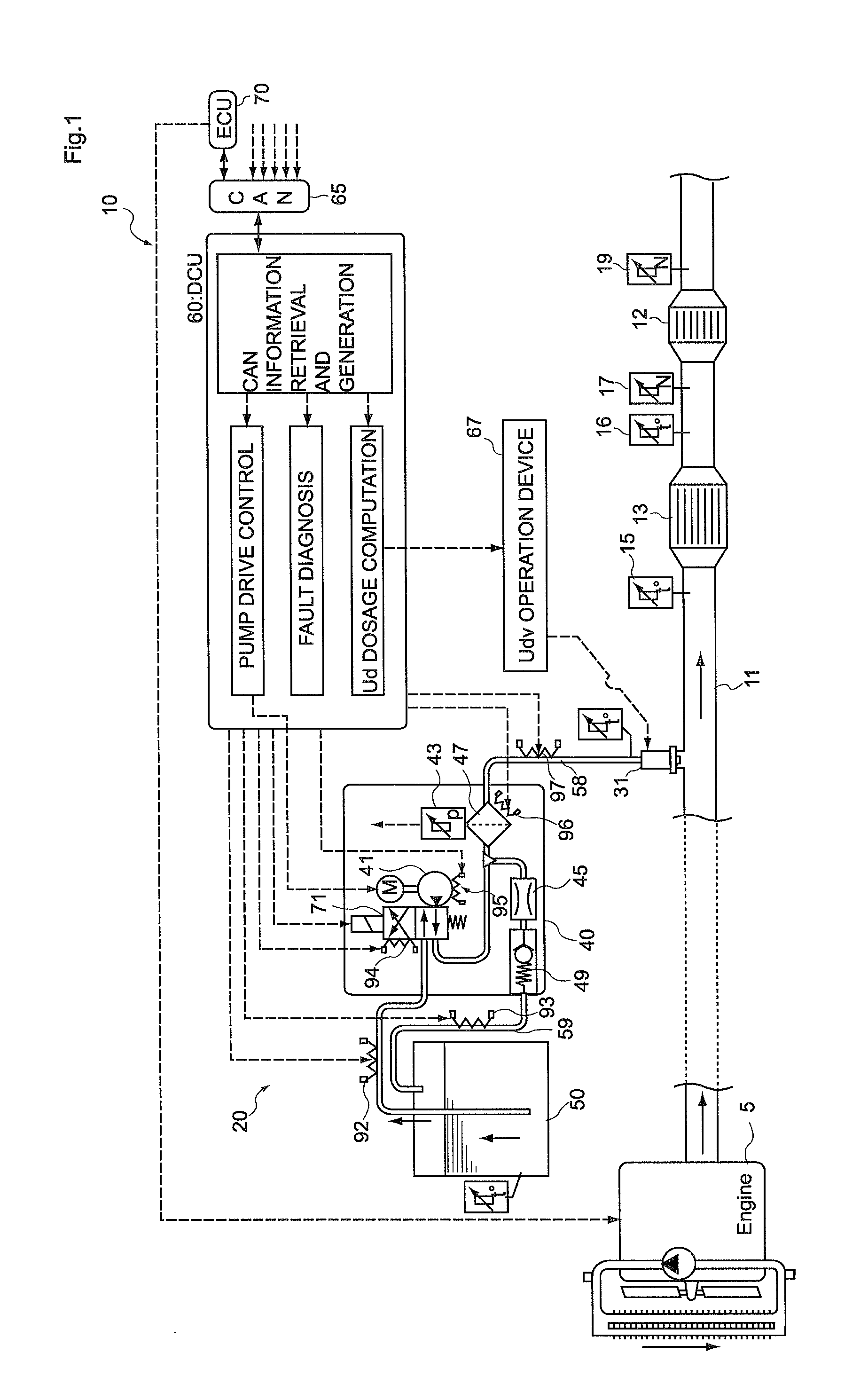
[0026]First, the basic configuration of an exhaust purification apparatus pertaining to a first embodiment of the present invention equipped with the oxidation catalyst fault diagnosis unit will be described with reference to FIG. 1.

[0027]An exhaust purification apparatus 10 shown in FIG. 1 is an exhaust purification apparatus 10 that injects and delivers an urea aqueous solution serving as a reducing agent to the upstream side of a reduction catalyst 13 disposed in an exhaust passage and selectively reduces and purifies NOx included in exhaust gas in the reduction catalyst 13. This exhaust purification apparatus 10 takes as its main elements and is equipped with the reduction catalyst 13 that is disposed in an exhaust pipe 11 connected to an internal combustion engine 5 and is for selectively reducing NOx included in the exhaust gas, a reducing agent delivery device 20 that includes a reducing agent injection valve 31 for injecting and delivering th...

second embodiment

[0083]Next, an exhaust purification apparatus equipped with an oxidation catalyst fault diagnosis unit pertaining to a second embodiment of the invention will be described. Whereas the exhaust purification apparatus of the first embodiment is equipped with NOx sensors on both the upstream side and the downstream side of the oxidation catalyst, the exhaust purification apparatus of the present embodiment differs from the exhaust purification apparatus of the first embodiment in that it is not equipped with a NOx sensor on the upstream side of the oxidation catalyst.

[0084]Description will be omitted below in regard to points shared in common with the first embodiment, and points differing from the first embodiment will be described.

[0085]As shown in FIG. 5, an exhaust purification apparatus 110 of the present embodiment is equipped with a NOx sensor 117 on the downstream side of the oxidation catalyst 12 and is not equipped with a NOx sensor on the upstream side of the oxidation catal...


PUM


Abstract

To provide an oxidation catalyst fault diagnosis unit and fault diagnosis method that can perform fault diagnosis of an oxidation catalyst with good precision in a desired time period and an internal combustion engine exhaust purification apparatus equipped with the oxidation catalyst fault diagnosis unit.An oxidation catalyst fault diagnosis unit which, in an exhaust purification apparatus of an internal combustion engine that delivers a reducing agent capable of generating ammonia to an exhaust passage on the upstream side of a reduction catalyst and selectively reduces and purifies NOx in exhaust with the reduction catalyst, is for performing fault diagnosis of an oxidation catalyst placed on the downstream side of the reduction catalyst, the oxidation catalyst fault diagnosis being equipped with a reducing agent dosage calculating portion that sets a dosage of the reducing agent such that a predetermined quantity of the ammonia flows out to the downstream side of the reduction catalyst, an oxidation efficiency calculating portion that obtains the efficiency with which the predetermined quantity of ammonia flowing out to the downstream side of the reduction catalyst is oxidized by the oxidation catalyst when the predetermined quantity of ammonia passes through the oxidation catalyst, and a fault determining portion that performs determination of whether or not the oxidation catalyst is faulty by comparing the oxidation efficiency with a predetermined reference value.

Description

TECHNICAL FIELD[0001]The present invention relates to an oxidation catalyst fault diagnosis unit and an oxidation catalyst fault diagnosis method and to an internal combustion engine exhaust purification apparatus. More particularly, the present invention relates to an oxidation catalyst fault diagnosis unit and an oxidation catalyst fault diagnosis method that perform fault diagnosis of an oxidation catalyst placed on the downstream side of a reduction catalyst that performs NOx reduction using ammonia and to an internal combustion engine exhaust purification apparatus.BACKGROUND ART[0002]Nitrogen oxides (NOx), which can have an impact on the environment, are included in exhaust gas emitted from internal combustion engines such as diesel engines. Conventionally, as one aspect of exhaust purification apparatus used for purifying these NOx, there are known SCR (Selective Catalytic Reduction) systems where a selective reduction catalyst is disposed in an exhaust passage and where redu...

Claims


Application Information

Patent Timeline
IPC IPC(8): F02B27/04F01N3/10F01N11/00
CPCF01N3/106F01N3/2066F01N11/00F01N2550/02F01N2560/026F01N13/009F01N2560/14F01N2610/02Y02T10/47Y02T10/24F01N2560/06Y02T10/12Y02T10/40
Inventor KASAHARA, HIROYUKI
Owner BOSCH CORP
Learn More