Roller follower, valve train, induction hardening apparatus, method of heat treatment of shaft member, method of manufacturing shaft, and shaft

Inactive Publication Date: 2010-12-23
NTN CORP
View PDF18 Cites 11 Cited by
  • Summary
  • Abstract
  • Description
  • Claims
  • Application Information

AI Technical Summary

Benefits of technology

[0077]As can clearly be understood from the description above, according to the roller follower and the valve train of the present invention, a roller follower achieving sufficiently improved durability and a valve train can be provided. In addition, according to the shaft as well as the induction hardening apparatus, the method of heat treatment of a shaft member, and the method of

Problems solved by technology

In this roller follower, occurrence of damage at a surface of an outer ring, an inner rin

Method used


Image

  • Roller follower, valve train, induction hardening apparatus, method of heat treatment of shaft member, method of manufacturing shaft, and shaft
  • Roller follower, valve train, induction hardening apparatus, method of heat treatment of shaft member, method of manufacturing shaft, and shaft
  • Roller follower, valve train, induction hardening apparatus, method of heat treatment of shaft member, method of manufacturing shaft, and shaft

Examples


embodiment 1

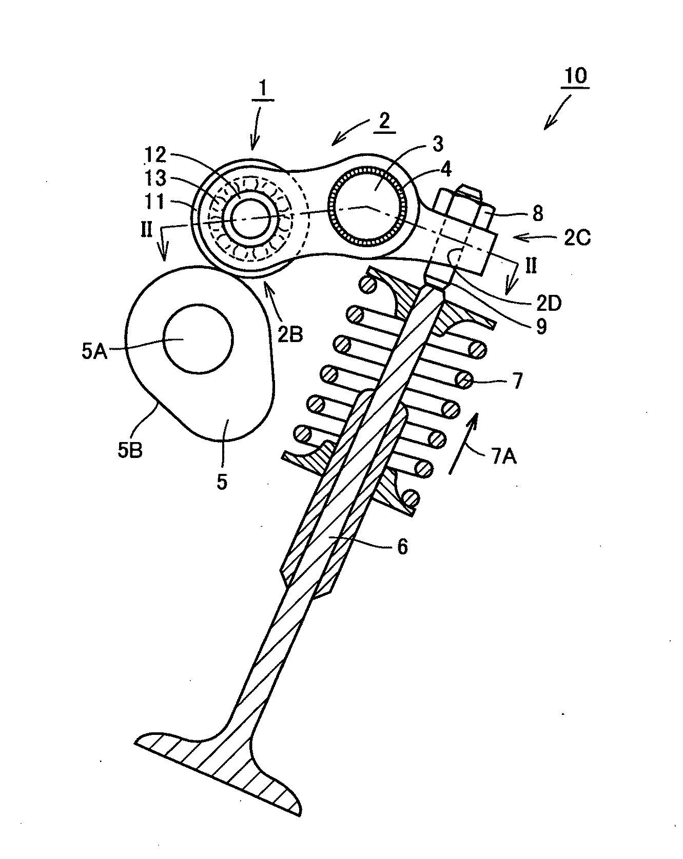
[0133]Initially, a valve train including a roller follower in Embodiment 1 will be described with reference to FIGS. 1 to 3.

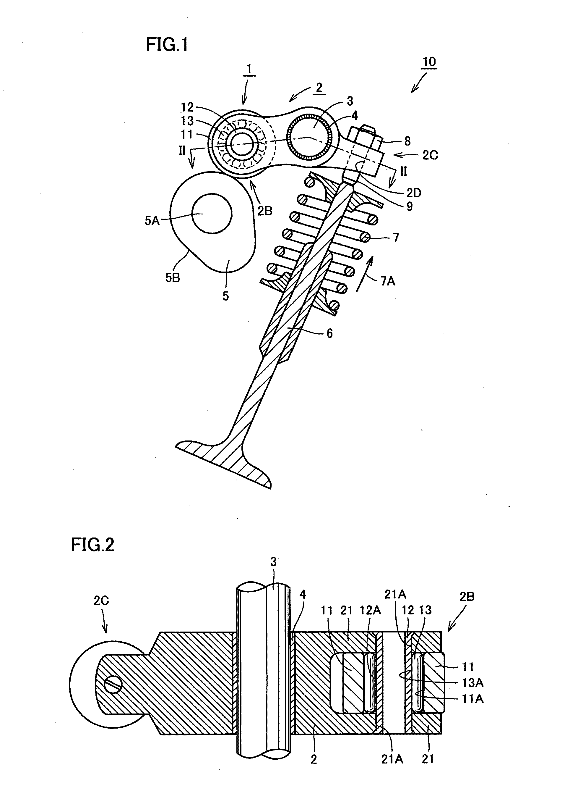
[0134]Referring to FIGS. 1 and 2, a valve train 10 includes a roller follower 1 which is a radial roller bearing of full-complement roller type, a rocker arm 2 serving as a holding member for holding roller follower 1 at one end portion 2B, a cam 5 arranged to be in contact, at its outer circumferential surface 5B, with an outer circumferential surface of a roller ring 11 serving as an outer ring of roller follower 1, an adjust screw 9 inserted in a through hole 2D formed in the other end portion 2C of rocker arm 2 and fixed to rocker arm 2 by means of a locknut 8, and a valve 6, which is an intake or exhaust valve of an engine, coupled at its one end portion to one end portion of adjust screw 9.

[0135]Referring to FIGS. 1 and 2, roller follower 1 includes annular roller ring 11 serving as the outer ring, a hollow cylindrical shaft 12 passing through roller ring...

embodiment 2

[0168]Embodiment 2 representing one embodiment of the present invention will now be described. Referring to FIGS. 1 to 3 and 9, valve train 10 and roller follower 1 in Embodiment 2 are basically structured and operate similarly to valve train 10 and roller follower 1 in Embodiment 1 and achieve similar effects. On the other hand, valve train 10 and roller follower 1 in Embodiment 2 are different from those in Embodiment 1 in a structure of an area where shaft 12 of roller follower 1 and rocker arm 2 are fixed to each other.

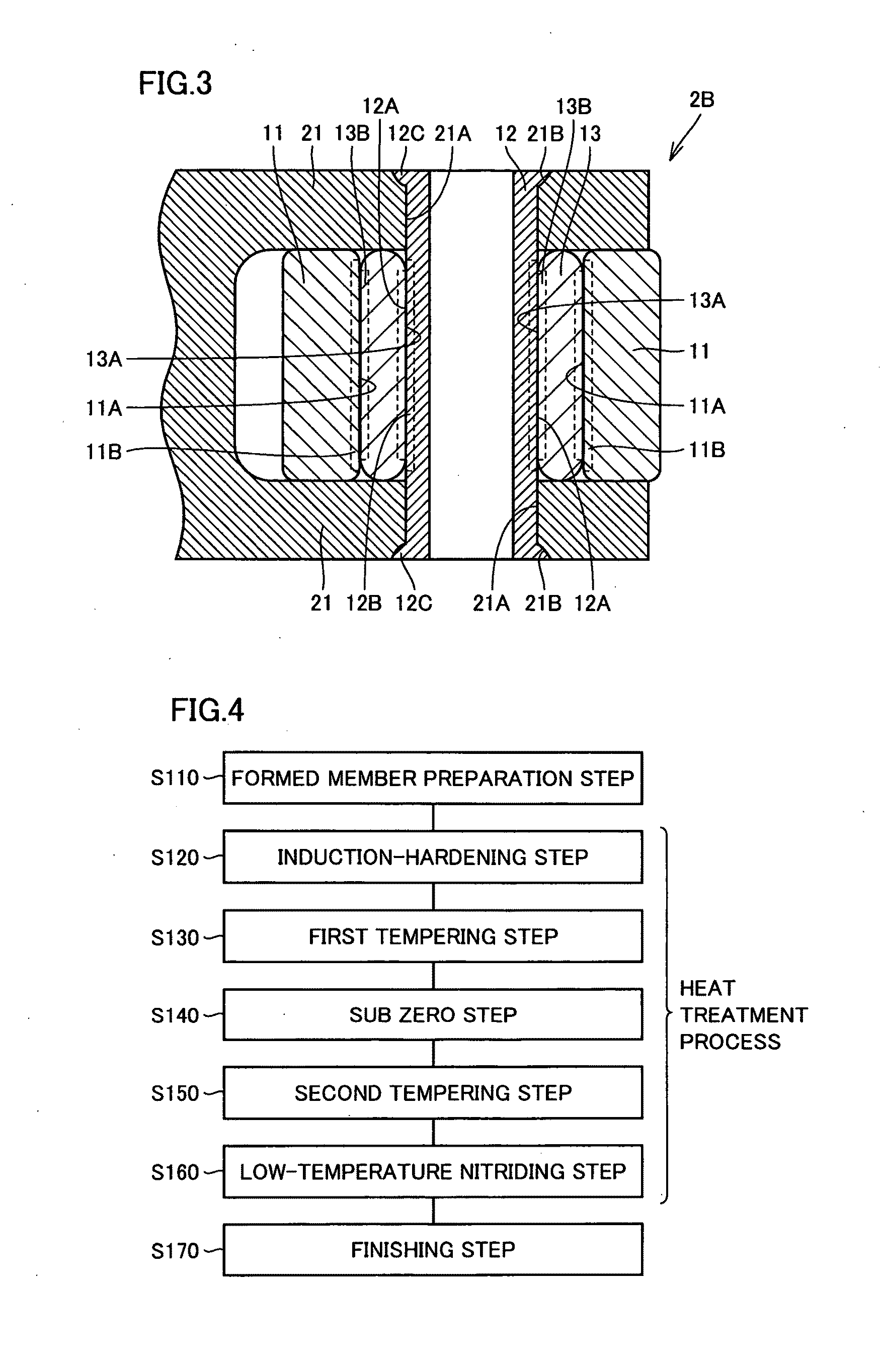
[0169]Namely, referring to FIG. 9, unlike Embodiment 1, tapered portion 21B is not formed in through hole 21A formed in the pair of sidewalls 21 of the rocker arm, and a diameter in a cross-section perpendicular to the direction of axis of shaft 12 is constant. In addition, unlike Embodiment 1, the opposing end portions of shaft 12 do not have low-hardness area 12C but shaft 12 as a whole has uniform hardness.

[0170]Valve train 10 and roller follower 1 in Embodimen...

embodiment 3

[0173]Embodiment 3 representing one embodiment of the present invention will now be described. Referring to FIGS. 1 to 3 and 10, valve train 10 and roller follower 1 in Embodiment 3 are basically structured and operate similarly to valve train 10 and roller follower 1 in Embodiment 1 and achieve similar effects. On the other hand, valve train 10 and roller follower 1 in Embodiment 3 are different from those in Embodiment 1 in a structure of an area where shaft 12 of roller follower 1 and rocker arm 2 are fixed to each other.

[0174]Namely, referring to FIG. 10, unlike Embodiment 1, tapered portion 21B is not formed in through hole 21A formed in the pair of sidewalls 21 of rocker arm 2, and instead, a projecting portion 21C projecting toward the center in a radial direction of through hole 21A is formed. In addition, as an end surface 12D of shaft 12 and projecting portion 21C above come in contact with each other, shaft 12 is fixed to rocker arm 2.

[0175]Valve train 10 and roller follo...


PUM

PropertyMeasurementUnit
Fractionaaaaaaaaaa
Fractionaaaaaaaaaa
Fractionaaaaaaaaaa

Abstract

A roller follower includes a roller ring, a shaft and a plurality of rollers. At least one of the roller ring, the shaft and the rollers is a steel member made of steel containing 0.7 to 2.4% carbon and 10.0 to 20.0% chromium, with remainder iron and impurities. In addition, carbide containing at least any one of iron and chromium as well as carbon and having an area of 12.6 μm2 or greater is generated at an area ratio of 5.0% or higher, at a rolling contact surface of the steel member (a roller ring rolling contact surface, a shaft rolling contact surface and a roller rolling contact surface).

Description

TECHNICAL FIELD[0001]The present invention relates to a roller follower, a valve train, an induction hardening apparatus, a method of heat treatment of a shaft member, a method of manufacturing a shaft, and a shaft, and more particularly to a roller follower interposed between a rocker arm and a cam for opening and closing a valve of an engine and arranged in contact with the cam and a valve train including the roller follower, as well as a shaft that can be used as a shaft of the roller follower, an induction hardening apparatus that can be used for manufacturing a shaft, a method of heat treatment of a shaft member, and a method of manufacturing a shaft.BACKGROUND ART[0002]In general, an intake valve or an exhaust valve of an engine of a car and the like is opened and closed by a valve train for transmitting rotation of a cam rotating together with a camshaft and operating the valve. Here, for the purpose of suppressing loss of kinetic energy and occurrence of wear of parts due to...

Claims


Application Information

Patent Timeline
IPC IPC(8): F01L1/18C21D1/10C22C38/00H05B6/04
CPCC21D1/10F16C33/62C21D1/42C21D6/002C21D6/02C21D6/04C21D9/40C22C38/36F01L1/14F01L1/16F01L1/18F01L2101/00F01L2103/00F01L2105/00F01L2105/02F16C19/46F16C33/34C21D1/25F16C2360/18F01L2301/00F01L2303/00F01L2305/00F01L2305/02Y02P10/25C22C38/34C22C38/44C22C38/46
Inventor FUJITA, TAKUMIOBAYASHI, KOUSUKE
Owner NTN CORP
Why Eureka
Try Eureka