
Phosphor converting ir leds

Inactive Publication Date: 2010-12-23
HONEYWELL INT INC
View PDF24 Cites 45 Cited by
  • Summary
  • Abstract
  • Description
  • Claims
  • Application Information

AI Technical Summary

Benefits of technology

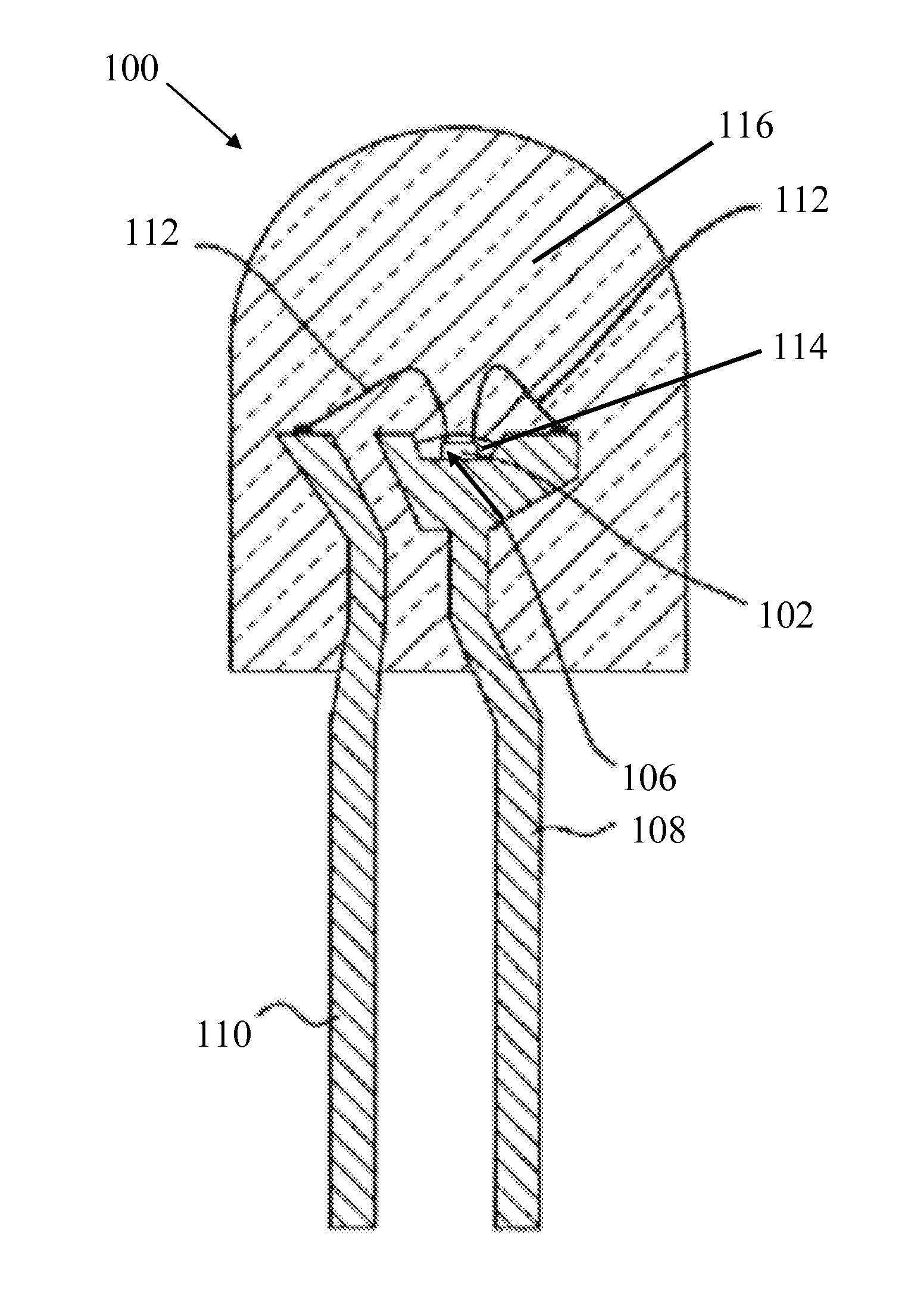
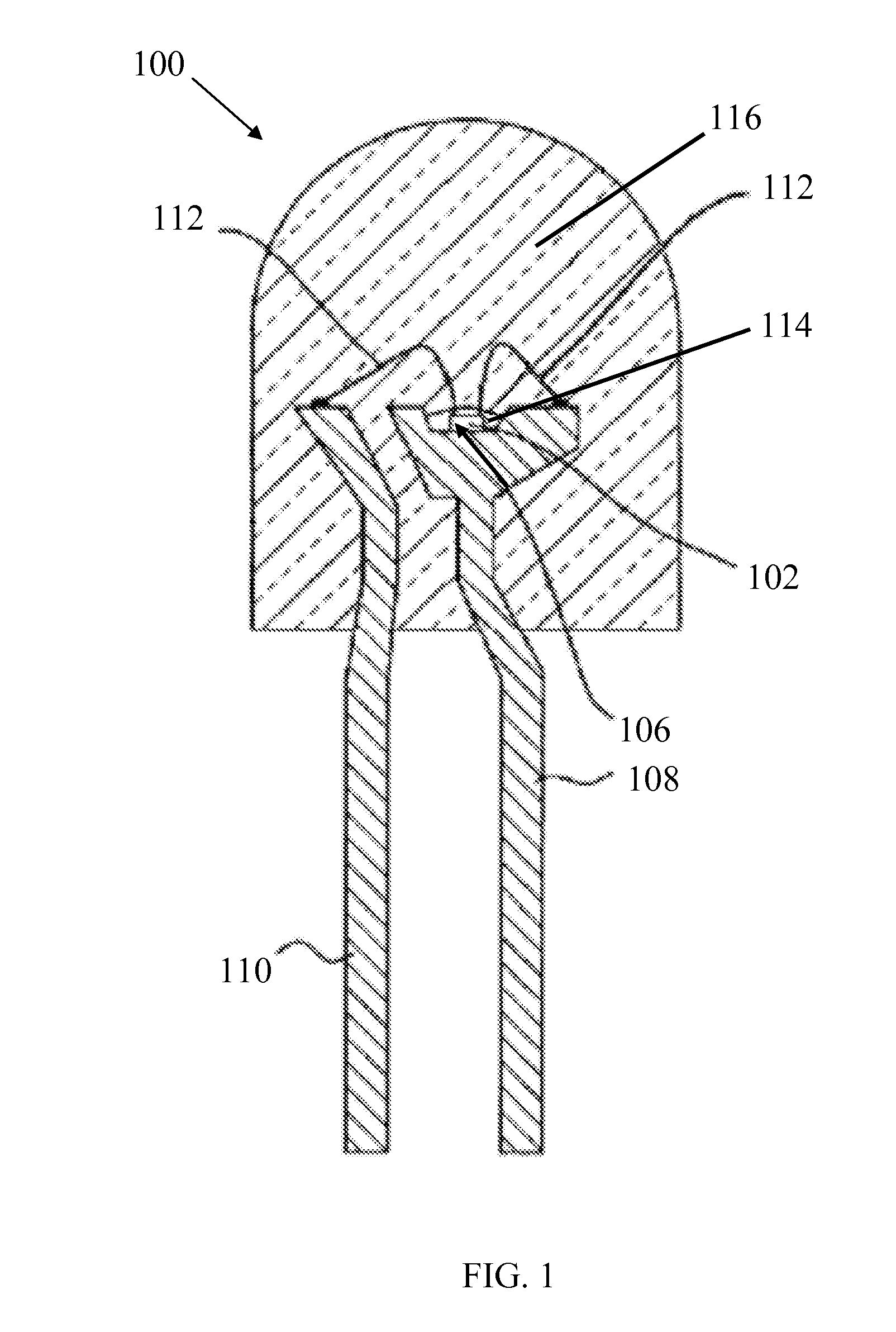
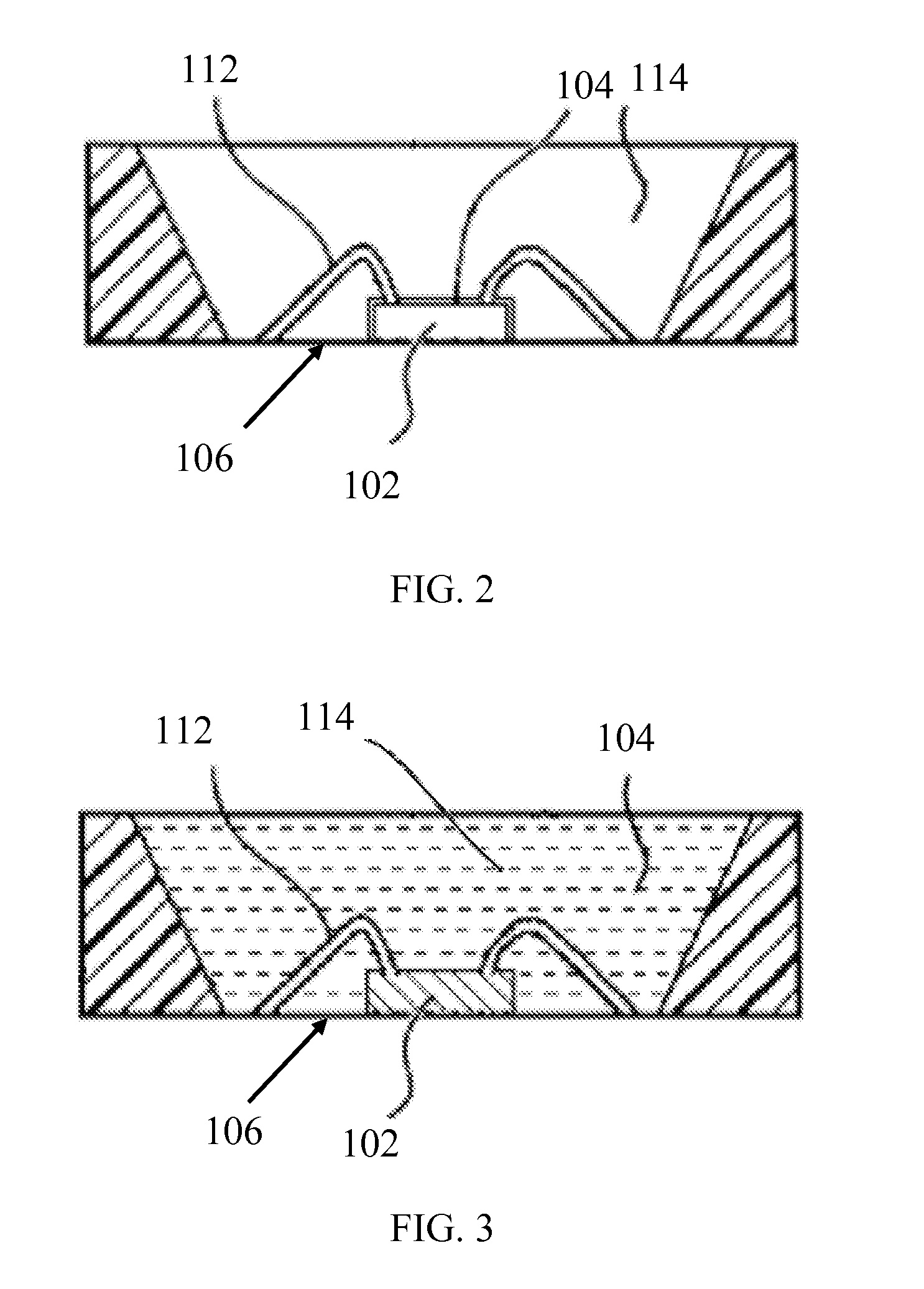
[0009]In another aspect, a stokes radiation emitting light emitting diode assembly is provided that includes: a) a mount lead comprising a recessed cup and a lead, b) a light emitting diode semiconductor chip mounted in the recessed cup of the mount lead, and c) a phosphor material on the light emitting diode semiconductor chip. The recessed cup optionally include a reflective metal capable of reflecting ultraviolet to infrared radiation. The light emitting diode semiconductor chip can have an electrode that is electrically connected to the mount lead, and the light emitting diode semiconductor chip can include a material that emits light having wavelengths ranging from the ultra-violet to the near infrared regions of the electromagnetic spectrum when excited by electrical energy. The phosphor material can include at least one infrared radiation emitting phosphor that absorbs light energy from said light emitting diode semiconductor chip and emits infrared radiation responsive to said absorbed light energy.

Problems solved by technology

Compared to visible light emitting LEDs, such conventional infrared light emitting LEDs generate infrared light that is significantly less intense, only emitting about 1 milliwatt per LED semiconductor chip due to an inability to create an effective band gap structure.

Method used


Image

  • Phosphor converting ir leds
  • Phosphor converting ir leds
  • Phosphor converting ir leds

Examples


example 1

[0046]A neodymium (Nd)-based phosphor with a 660 nm LED chip pump. The phosphor consists of a host lattice material of yttrium gallium garnet that includes a chromium sensitizer that absorbs the 660 nm LED chip pump emission and then transfers that energy, with high quantum efficiency, to the neodymium ions. The emission spectrum is graphically illustrated in FIG. 5.

example 2

[0047]An ytterbium (Yb)-based phosphor with an 660 nm LED chip pump. The phosphor consists of a host lattice material of yttrium gallium garnet that includes a chromium sensitizer that absorbs the 660 nm LED chip pump emission and then transfers that energy, with high quantum efficiency, to the ytterbium ions. The emission spectrum is graphically illustrated in FIG. 6.

example 3

[0048]An erbium (Er)-based phosphor with a 660 nm LED chip pump. The phosphor consists of a host lattice material of yttrium gallium garnet that includes a chromium sensitizer that absorbs the 660 nm LED chip pump emission and then transfers that energy, with high quantum efficiency, to the erbium ions. The emission spectrum is graphically illustrated in FIG. 7.


PUM


Abstract

The production of light of various wavelengths using IR phosphor down conversion techniques using existing LED emissions to pump sensitizer-rare earth ions that emit at other wavelengths. A sensitizer absorbs an LED chip pump emission and then transfers that energy with high quantum efficiency to dopant ions that then emits at their characteristic wavelength.

Description

RELATED APPLICATIONS[0001]This application claims the benefit of U.S. Provisional Application Ser. No. 61 / 218531, filed on Jun. 19, 2009, currently pending, which is hereby incorporated by reference in its entirety.FIELD OF THE INVENTION[0002]The present technology relates to light emitting devices. More particularly, the present technology pertains to light emitting semiconductor structures coated with one or more infrared light emitting phosphors.DESCRIPTION OF THE RELATED ART[0003]Light emitting diodes (LEDs) are p-n junction devices that convert an incoming flow of electric energy into an outgoing flow of electromagnetic radiation. LEDs emit electromagnetic radiation in ultraviolet, visible or infrared regions of the electromagnetic spectrum, where the emission wavelength typically depends on the diode semiconductor chip materials from which they are produced. For example, LEDs formed from aluminum gallium arsenide containing semiconductor chip materials are known to emit red vi...

Claims


Application Information

Patent Timeline
IPC IPC(8): H01L33/50H01L33/08
CPCH01L33/50H01L33/44H01L2224/45144H01L2224/48091H01L2224/48247H01L2224/48257H01L2224/8592H01L2924/181H01L2924/18165H01L2924/00012H01L2924/00014H01L2924/00H01L33/501H01L33/58
Inventor RAPOPORT, WILLIAM ROSSKANE, JAMESCASTELINO, KIRIN T.
Owner HONEYWELL INT INC
Learn More