X-ray detector for phase contrast imaging

a phase contrast and detector technology, applied in the field of x-ray detectors, can solve the problems of not being able to directly spatially resolve patterns, the pixel size of existing x-ray detectors is (much) larger than the distance between maxima, and the movement of optical elements is a nontrivial mechanical task

Inactive Publication Date: 2010-12-23
KONINKLIJKE PHILIPS ELECTRONICS NV
View PDF5 Cites 32 Cited by
  • Summary
  • Abstract
  • Description
  • Claims
  • Application Information

AI Technical Summary

Benefits of technology

[0008]The described X-ray detector has the advantage to allow a sampling of an X-ray (intensity) pattern impinging on it simultaneously with at least two analyzer gratings of different characteristics. As will be described in more detail below, such an X-ray detector can particularly be used for generating phase contrast X-ray images of an object without a need to move two optical elements with respect to each other.
[0017]The described X-ray device has the advantage to process an intensity pattern that is generated by the DOE simultaneously with analyzer gratings of different characteristics. Thus the requirement of a relative movement between the DOE and a (global) analyzer grating in front of the sensitive elements can be avoided.
[0023]The X-ray source may optionally comprise at least one filter, e.g. a filter which suppresses a certain band of the X-ray spectrum emitted by the X-ray source. Parts of the X-ray spectrum that are of no use for the desired phase contrast imaging or that even disturb such an imaging can thus be filtered out. This helps to minimize the exposure of the object to X-radiation, which is particularly important in medical applications.
[0025]The method allows to process an intensity pattern locally in different ways at the same time, i.e. with analyzer gratings of different characteristics. As was described above, this is particularly advantageous in the generation of X-ray phase contrast images of an object during which said object is irradiated with X-radiation and an interference pattern is generated with a DOE disposed behind the object.

Problems solved by technology

A problem of the described approach is that the feasible pixel size of existing X-ray detectors is (much) larger than the distance between the maxima and minima of the interference pattern.
These patterns can therefore not directly be spatially resolved.
The necessary movement of optical elements is however a nontrivial mechanical task, particularly if it has to be done fast and with high accuracy, as would be required if phase contrast imaging shall be applied in a medical environment.
In addition, bringing the grid into different positions costs time so that imaging of moving objects (e.g. the beating heart) may suffer from blurring due to motion artifacts.

Method used


Image

  • X-ray detector for phase contrast imaging
  • X-ray detector for phase contrast imaging
  • X-ray detector for phase contrast imaging

Examples


Embodiment Construction

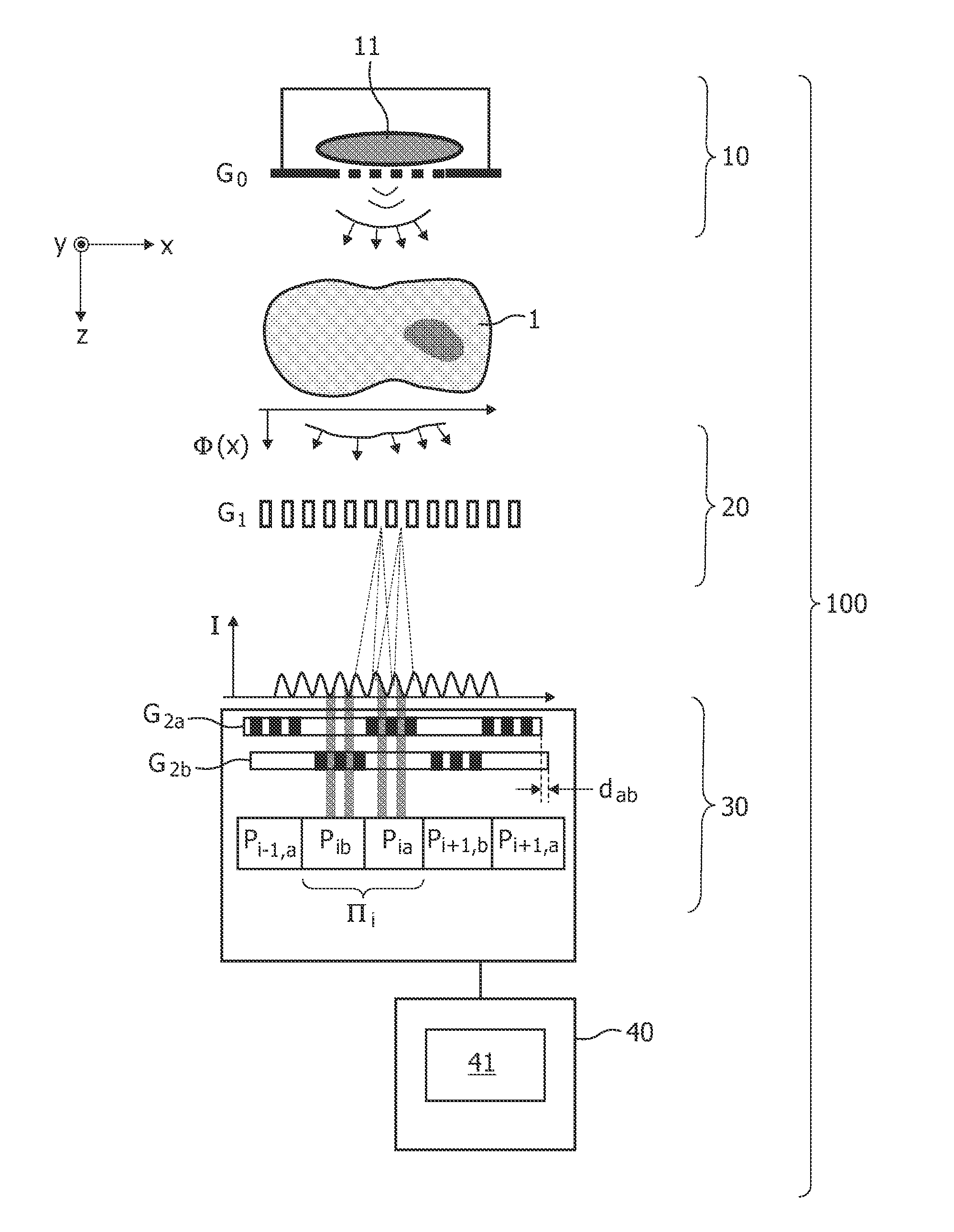
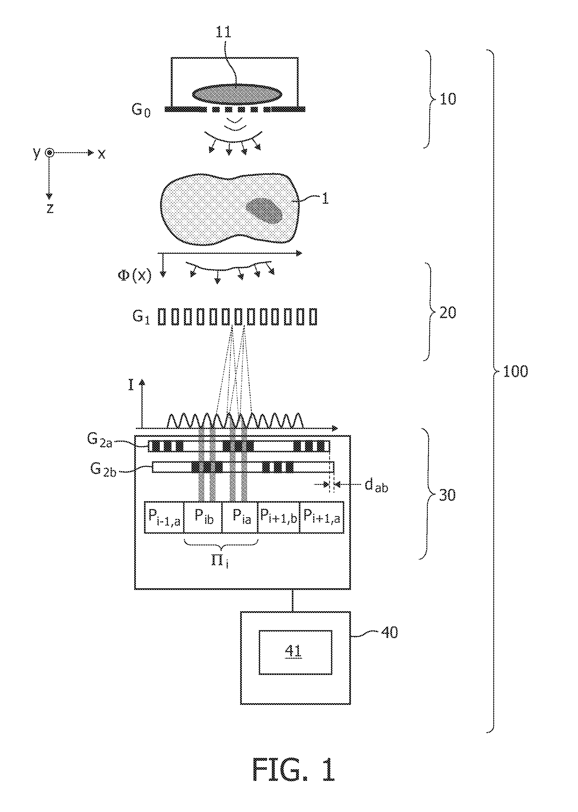
[0034]Regarding an X-ray beam as electromagnetic wave with small wavelength, the effect of matter on traversing X-rays can be described by a complex refractive index n=1−δ−iβ. Usually, X-ray imaging refers to the imaginary part iβ of the refractive index, i.e. attenuation of the X-ray fluence by the object under investigation is considered.

[0035]However, X-ray imaging of the phase-shift δ is also possible. In fact, the effect of biological tissue on the phase shift δ is much higher than on the absorption component. This makes soft tissue imaging an attractive application of phase contrast imaging (PCI). It is also important to consider that contrast is not correlated with absorbed X-ray dose. This could make X-ray imaging a low dose modality which is especially important for X-ray CT.

[0036]For years PCI has only been studied in research activities. Then, a simple realization of PCI (to be more specific “differential PCI”) has been shown which could also be employed for medical imagi...


PUM

PropertyMeasurementUnit
phase contrastaaaaaaaaaa
phase shiftaaaaaaaaaa
phase contrast imagingaaaaaaaaaa

Abstract

The invention relates to an X-ray detector (30) that comprises an array of sensitive elements (Pi−1,b, Pia, Pib, Pi+1,a, Pi+1,b) and at least two analyzer gratings (G2a, G2b) disposed with different phase and / or periodicity in front of two different sensitive elements. Preferably, the sensitive elements are organized in macro-pixels (IIi) of e.g. four adjacent sensitive elements, where analyzer gratings with mutually different phases are disposed in front said sensitive elements. The detector (30) can particularly be applied in an X-ray device (100) for generating phase contrast images because it allows to sample an intensity pattern (I) generated by such a device simultaneously at different positions.

Description

FIELD OF THE INVENTION[0001]The invention relates to an X-ray detector, an X-ray device comprising such a detector, and a method for analyzing an X-ray intensity pattern, particularly for generating phase contrast X-ray images of an object.BACKGROUND OF THE INVENTION[0002]While classical X-ray imaging measures the absorption of X-rays caused by an object, phase contrast imaging aims at the detection of the phase shift X-rays experience as they pass through an object. According to a design that has been described in the literature (T. Weitkamp et al., “X-ray phase imaging with a grating interferometer”, Optics Express 13(16), 2005), a phase grating is placed behind an object to generate an interference pattern of intensity maxima and minima when the object is irradiated with (coherent) X-rays. Any phase shift in the X-ray waves that is introduced by the object causes some characteristic displacement in the interference pattern. Measuring these displacements therefore allows to recons...

Claims


Application Information

Patent Timeline
Patent Type & Authority Applications(United States)
IPC IPC(8): G01N23/04G01J1/00
CPCG21K1/06G21K2207/005G21K2201/067
Inventor BAEUMER, CHRISTIANENGEL, KLAUS JUERGENHERRMANN, CHRISTOPH
Owner KONINKLIJKE PHILIPS ELECTRONICS NV
Why Eureka
Try Eureka