Vehicle equipped with power storage device and temperature control method of power storage device

a technology of power storage device and power storage device, which is applied in the field of vehicles, can solve the problems of battery temperature not always the temperature suitable for charging, battery capacity that can be installed, and poor charging efficiency

Active Publication Date: 2010-12-23
TOYOTA JIDOSHA KK +1
View PDF24 Cites 84 Cited by
  • Summary
  • Abstract
  • Description
  • Claims
  • Application Information

AI Technical Summary

Benefits of technology

[0018]In accordance with the present invention, it is possible to start externally

Problems solved by technology

Even for such externally chargeable vehicles, the battery capacity that can be installed is limited, and therefore it is often desired that charging is started as soon as the vehicle arrives at a destination if the dest

Method used


Image

  • Vehicle equipped with power storage device and temperature control method of power storage device
  • Vehicle equipped with power storage device and temperature control method of power storage device
  • Vehicle equipped with power storage device and temperature control method of power storage device

Examples


first embodiment

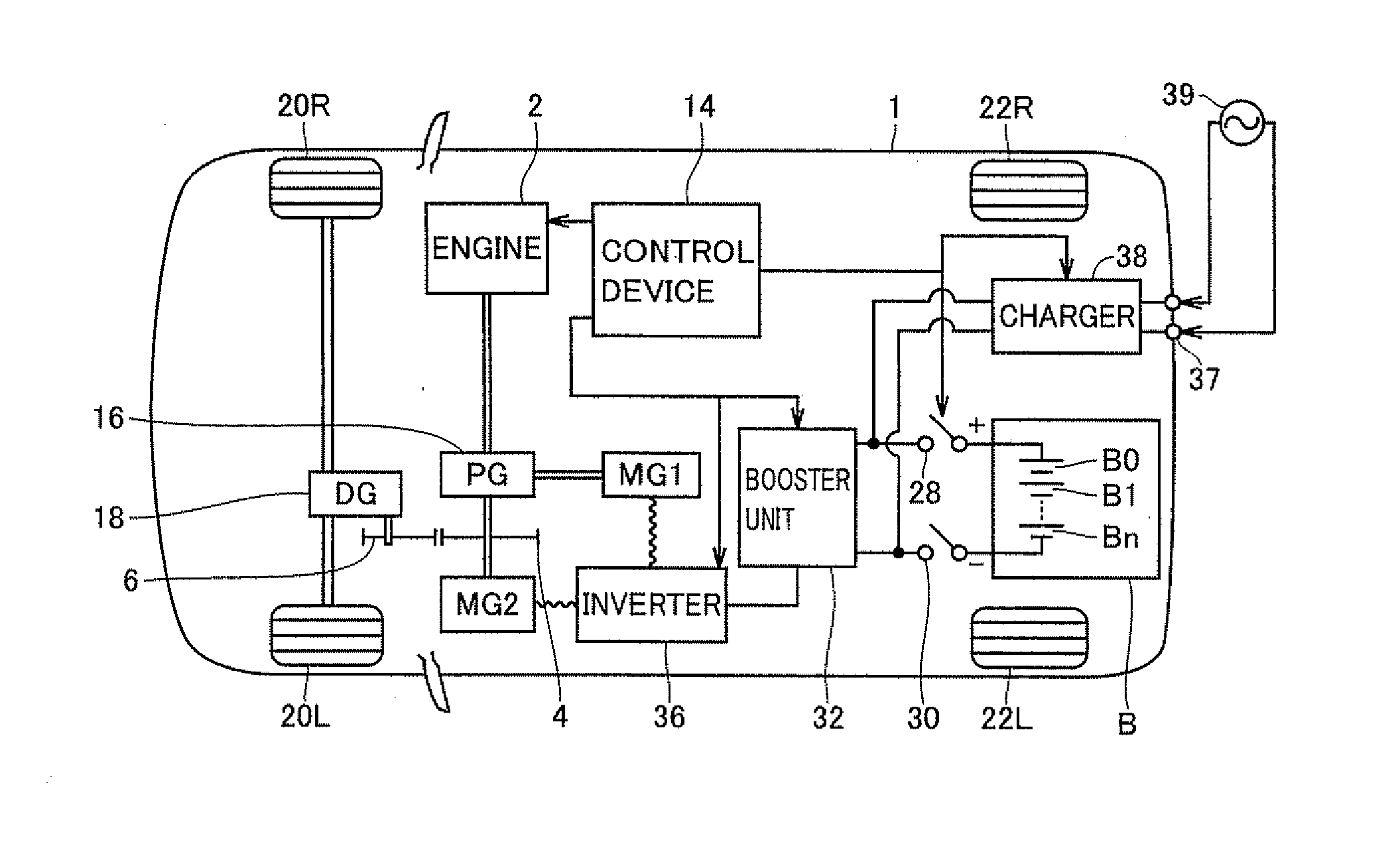
[0033]FIG. 1 is a diagram showing a main configuration of a hybrid vehicle 1 in the present embodiment, Hybrid vehicle 1 is a vehicle using an engine and a motor in combination for driving.

[0034]Referring to FIG. 1, hybrid vehicle 1 includes front wheels 20R, 20L, rear wheels 22R, 22L, an engine 2, a planetary gear 16, a differential gear 18, and gears 4, 6.

[0035]Hybrid vehicle 1 further includes a battery B arranged at the rear of the vehicle, a booster unit 32 increasing the voltage of DC power output by battery B, an inverter 36 sending / receiving DC power to / from booster unit 32, a motor generator MG1 coupled to engine 2 through planetary gear 16 for mainly generating electric power, and a motor generator MG2 having a rotation shaft connected with planetary gear 16. Inverter 36 is connected to motor generators MG1, MG2 for carrying out conversion between DC power from booster unit 32 and AC power.

[0036]Planetary gear 16 has first to third rotation shafts. The first rotation shaft...

second embodiment

[0112]In the first embodiment, the outside air temperature measured by the outside air sensor is considered as a factor that affects the temperature of the battery. However, at a remote destination, the outside air temperature may significantly be different from a departure place. In addition, as other factors, weather, altitude, time in the neighborhood of the destination may also affect the battery temperature.

[0113]FIG. 12 is a diagram illustrating an example in which environments are different between a destination and a departure place.

[0114]Referring to FIG. 12, although the weather is fine and the air temperature is 30° C. at the departure place, if the destination is the area along the mountains, the weather may be greatly different. In FIG. 12, at the destination, the weather is rain and the air temperature is 15° C. In order to perform the battery temperature control, it may be late to detect such differences in weather and air temperature with the outside air temperature ...


PUM


Abstract

A vehicle includes a battery as a power storage device that can be charged and discharged, a booster unit, an inverter, and a motor generator operating as a vehicle driving unit receiving electric power supply from the battery to drive the vehicle, a coupling unit coupling the vehicle with an external power supply for charging the battery from the outside of the vehicle, and a control device performing control related to the battery. The control device determines whether or not a destination is a charging-available place where the battery can be charged from the outside of the vehicle, and if the destination is a charging-available place, performs control related to the battery so that the temperature of the battery is a charging-efficient temperature on arrival at the destination.

Description

TECHNICAL FIELD[0001]The present invention relates to a vehicle, and more particularly to a vehicle equipped with a power storage device chargeable from the outside of the vehicle and a temperature control method of the power storage device.BACKGROUND ART[0002]In recent years, electric cars, hybrid vehicles, and the like equipped with motors as driving devices and equipped with batteries supplying electric power for driving the motors attract attention as environmentally friendly vehicles. Concerning such hybrid vehicles, Japanese Patent Laying-Open No. 2006-139963 discloses a battery cooling device capable of holding a battery temperature in an appropriate temperate range.[0003]This battery cooling device includes a cooling fan cooling a high voltage battery mounted on a vehicle, a car navigation system setting a driving route of the vehicle and also obtaining road information and traffic information about the set driving route, a temperature sensor detecting the temperature of the...

Claims


Application Information

Patent Timeline
IPC IPC(8): G06F7/00B60L11/18B60K6/445B60W10/26H01M10/44H01M10/60H01M10/613H01M10/615H01M10/625H01M10/633H01M10/6563H01M10/6571H01M10/663H02J7/00H02J7/04
CPCB60W2720/10Y02T90/32H01M10/486H01M10/5004H01M10/5006H01M10/5016H01M10/502H01M10/5022H01M10/5024H01M10/5067H01M10/5083H01M10/5095H01M16/006H01M2250/20Y02T10/6217Y02T10/6239Y02T10/6269Y02T10/6291Y02T10/7005Y02T10/7044Y02T10/705Y02T10/7077Y02T10/7283Y02T10/7291Y02T90/14Y02T90/16Y02T90/162B60K1/02B60K6/445B60L11/123B60L11/14B60L11/1816B60L11/1861B60L11/187B60L11/1872B60L15/2045B60L2240/20B60L2240/441B60L2240/62B60L2240/662B60L2260/56B60W10/06B60W10/08B60W10/26B60W20/00B60W20/102B60W2510/0638B60W2510/244B60W2510/246B60W2520/10B60W2520/14B60W2540/10B60W2550/12B60W2550/402B60W2710/086B60W2710/246H01M10/443H01M10/625H01M10/63H01M10/615H01M10/633H01M10/663H01M10/6563H01M10/6571H01M10/635H01M10/613B60W20/11Y02T10/7072Y02T10/72B60L53/14B60L50/61B60L50/16B60L58/12B60L58/24B60L58/25B60W2555/20B60W2556/50Y02T10/62Y02T10/70Y02T10/64Y02T90/40Y02E60/50Y02E60/10B60W50/0097B60W2050/146B60W20/12
Inventor IIDA, TAKAHIDETAKAHARA, MASATOSHIKIMURA, KEISUKE
Owner TOYOTA JIDOSHA KK
Why Eureka
Try Eureka