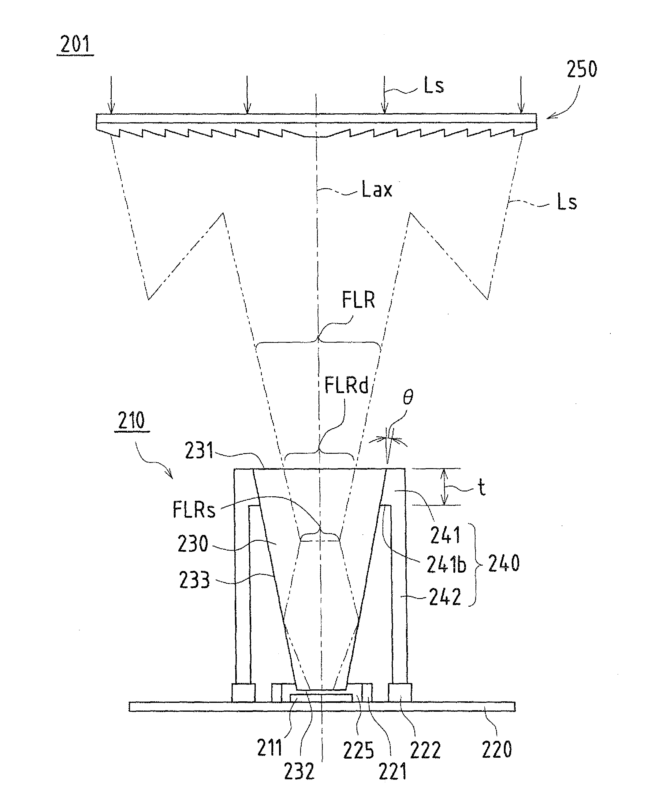
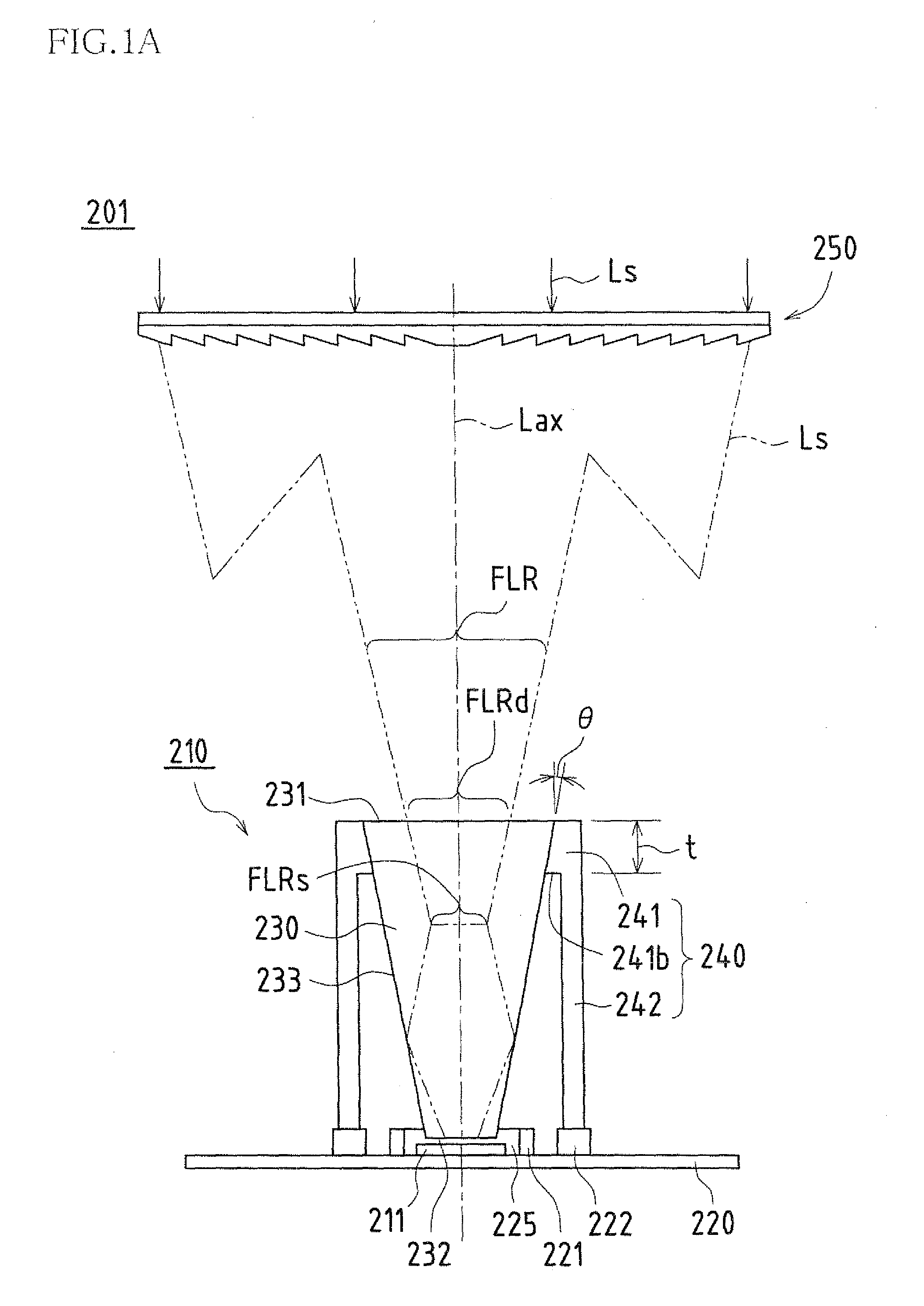
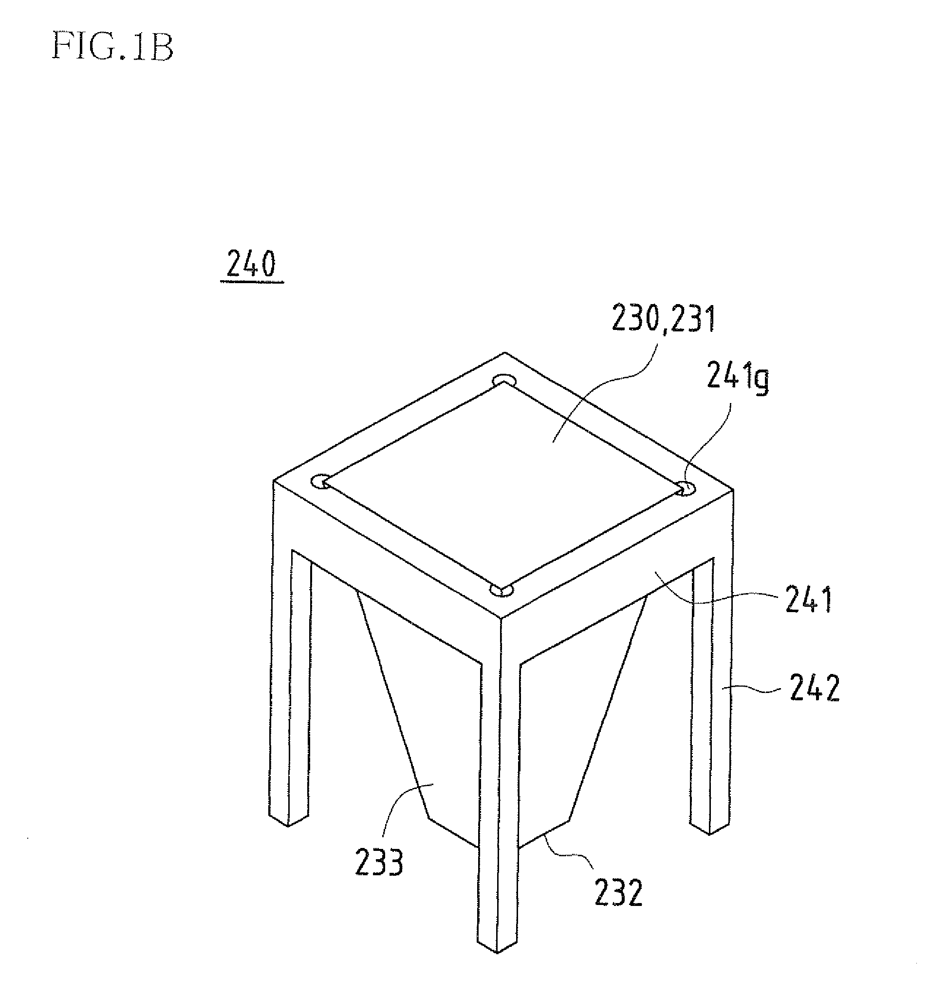
[0071]The first solar cell of the present invention is a solar cell including: a solar cell element that photoelectrically converts sunlight concentrated by a concentrating lens; a
receiver substrate on which the solar cell element is placed; a columnar optical member having an incidence surface on which the concentrated sunlight is incident and an
irradiation surface that is disposed facing the solar cell element and that irradiates sunlight to the solar cell element; and a holding portion that is provided in a standing manner on the receiver substrate and that holds the columnar optical member, wherein the holding portion includes a frame-shaped abutting frame member that is abutted against a side surface of the columnar optical member and that is configured to have a thickness in a direction from the incidence surface to the irradiation surface, and a support that is disposed away from the columnar optical member and that supports the abutting frame member, the side surface is inclined such that incident sunlight is totally reflected in a direction of the irradiation surface, and the incidence surface is configured of a size such that an incidence surface concentrated
light beam region that is formed on the incidence surface by a concentrated light beam region formed by the concentrated sunlight is locatable inside the incidence surface. Accordingly, it is possible to achieve an effect of enabling the incidence surface concentrated light beam region to be reliably located within the region of the incidence surface to prevent fluctuation of the light-concentrating characteristics when the concentrated sunlight (concentrated light beam region) has undergone positional shift with respect to the center of the columnar optical member, and also allowing heat applied by concentrated sunlight on the columnar optical member to be dispersed in the surrounding region by the side surface and the abutting frame member, so that it is possible to provide a highly heat-resistant and reliable solar cell having improved light-concentrating efficiency and
photoelectric conversion efficiency.
[0072]The first concentrating solar power generation module of the present invention is a concentrating solar power generation module including: a concentrating lens that concentrates and causes sunlight to be incident on the solar cell; and a solar cell that photoelectrically converts the sunlight concentrated by the concentrating lens, wherein the solar cell is the first solar cell according to the present invention. Accordingly, the concentrating efficiency will not be reduced even if the incidence surface concentrated light beam region formed by concentrated sunlight on the incidence surface has undergone positional shift with respect to the center of the incidence surface, so that it is possible to provide a highly heat-resistant and highly reliable concentrating solar power generation module having improved light-concentrating efficiency and conversion efficiency.
[0073]The first solar cell manufacturing method of the present invention is a solar cell manufacturing method for manufacturing a solar cell including: a solar cell element that photoelectrically converts sunlight concentrated by a concentrating lens; a receiver substrate on which the solar cell element is placed; a columnar optical member having an incidence surface on which the concentrated sunlight is incident and an irradiation surface that is disposed facing the solar cell element and that irradiates sunlight to the solar cell element; and a holding portion provided in a standing manner on the receiver substrate, the holding portion including a frame-shaped abutting frame member abutted against a side surface of the columnar optical member and a support that is disposed away from the columnar optical member and that supports the abutting frame member, the method including: a substrate preparation step of preparing the receiver substrate on which the solar cell element is placed; a resin stopper portion formation step of applying an
adhesive resin to the receiver substrate to form an inner resin stopper portion into which a translucent resin for sealing the solar cell element with resin will be injected and an outer resin stopper portion to which the support will be fixed outside the inner resin stopper portion; a support fixation step of fixing the support to the receiver substrate by bonding the support to the outer resin stopper portion and curing the
adhesive resin; a translucent resin injection step of injecting the translucent resin inside the inner resin stopper portion; a columnar optical member placement step of placing the irradiation surface on the translucent resin with the columnar optical member abutted against the abutting frame member; and a resin sealing portion formation step of curing the translucent resin to form a resin sealing portion. Accordingly, it is possible to enable the incidence surface concentrated light beam region to be located within the region of the incidence surface to prevent fluctuation of the light-concentrating characteristics when concentrated sunlight (concentrated light beam region) has undergone positional shift with respect to the center of the columnar optical member, and also to allow the heat applied by concentrated sunlight to the columnar optical member to be dispersed by the abutting frame member, so that it is possible to achieve an effect of manufacturing a highly heat-resistant and reliable solar cell having improved light-concentrating efficiency and
photoelectric conversion efficiency with ease and high accuracy.
[0074]The second solar cell of the present invention is a solar cell including: a solar cell element that photoelectrically converts sunlight concentrated by a concentrating lens; a receiver substrate on which the solar cell element is placed; and a resin sealing portion for sealing the solar cell element with resin, wherein the solar cell further includes a columnar optical member forming a light-guiding path for guiding the concentrated sunlight to the solar cell element, and an optical holding portion that has a holding wall for holding the columnar optical member and that is placed on the receiver substrate so as to cover the resin sealing portion. Accordingly it is possible to secure a light-guiding path having high positional accuracy and stability and achieve light-concentrating characteristics by which sunlight can be concentrated highly accurately over a large
wavelength range, so that it is possible to obtain an effect of improving the light-concentrating characteristics and the heat dissipation and increasing the power generation efficiency and the power generation by preventing a reduction in power generation efficiency and a temperature increase resulting from positional shift of concentrated sunlight, thus improving the heat-resistance, reliability and weather-resistance.
[0075]The second concentrating solar power generation module of the present invention is a concentrating solar power generation module including: a concentrating lens that concentrates sunlight; and a solar cell that photoelectrically converts sunlight concentrated by the concentrating lens, wherein the solar cell is the second solar cell according to the present invention. Accordingly, it is possible to secure a light-guiding path having high positional accuracy and stability and achieve light-concentrating characteristics by which sunlight can be concentrated highly accurately over a large
wavelength range, so that it is possible to obtain an effect of improving the light-concentrating characteristics and the heat dissipation and increasing the power generation efficiency and the power generation by preventing a reduction in power generation efficiency and a temperature increase resulting from positional shift of concentrated sunlight, thus improving the heat-resistance, reliability and weather-resistance.
[0076]The second solar cell manufacturing method of the present invention is a solar cell manufacturing method for manufacturing a solar cell including: a solar cell element that photoelectrically converts sunlight concentrated by a concentrating lens; a receiver substrate on which the solar cell element is placed; a resin sealing portion for sealing the solar cell element with resin; a columnar optical member forming a light-guiding path for guiding the concentrated sunlight to the solar cell element; and an optical holding portion that has a holding wall for holding the columnar optical member and that is placed on the receiver substrate so as to cover the resin sealing portion, the method including: an optical holding portion preparation step of preparing the optical holding portion by forming
metal; an optical holding portion placement step of placing the optical holding portion so as to abut against the receiver substrate at the outer periphery of the solar cell element; a resin injection step of injecting a sealing resin for forming the resin sealing portion into a space formed by the optical holding portion and the receiver substrate; and an optical member placement step of placing the columnar optical member on the holding wall. Accordingly, it is possible to position the optical holding portion with the columnar optical member highly accurately by a simple process, and the light-guiding path for effectively guiding the sunlight with high accuracy and the optical holding portion can be formed easily, so that it is possible to obtain an effect of manufacturing, with good productivity and low cost, a highly heat-resistant, reliable and weather-resistant solar cell having improved light-concentrating characteristics and heat dissipation that provides improved power generation efficiency and power generation by preventing a reduction in power generation efficiency and a temperature increase resulting from positional shift of concentrated sunlight.


