Light source device and projector

a light source device and projector technology, applied in the direction of fluorescence/phosphorescence, optical radiation measurement, instruments, etc., can solve the problems of labor-intensive manufacturing of light source devices, color purities deterioration, and increase in cost, so as to achieve high color purity, easy manufacturing, and simple configuration

Active Publication Date: 2010-12-30
CASIO COMPUTER CO LTD
View PDF1 Cites 166 Cited by
  • Summary
  • Abstract
  • Description
  • Claims
  • Application Information

AI Technical Summary

Benefits of technology

[0013]The present invention was developed in consideration of such problems in the background art. One of objects of the invention is to provide a light source device in which a fluorescent wheel itself is formed as a reflective plate without providing its fluorescent wheel surface with any special reflective layer for reflecting only light of a specific wavelength band, while a transmissive portion which can transmit source light is provided in

Problems solved by technology

Manufacturing the light source device therefore becomes labor-consuming, causing increase in cost.
Therefore, there may be a problem that color purities deteriorate.
In addition, since the incidence surface and the emission surface of the blue wavelength light in the flu

Method used


Image

  • Light source device and projector
  • Light source device and projector
  • Light source device and projector

Examples


Embodiment Construction

[0023]An embodiment according to the present invention will be described in detail with reference to the accompanying drawings. The scope of the claimed invention should not be limited to the examples illustrated in the drawings and those described below.

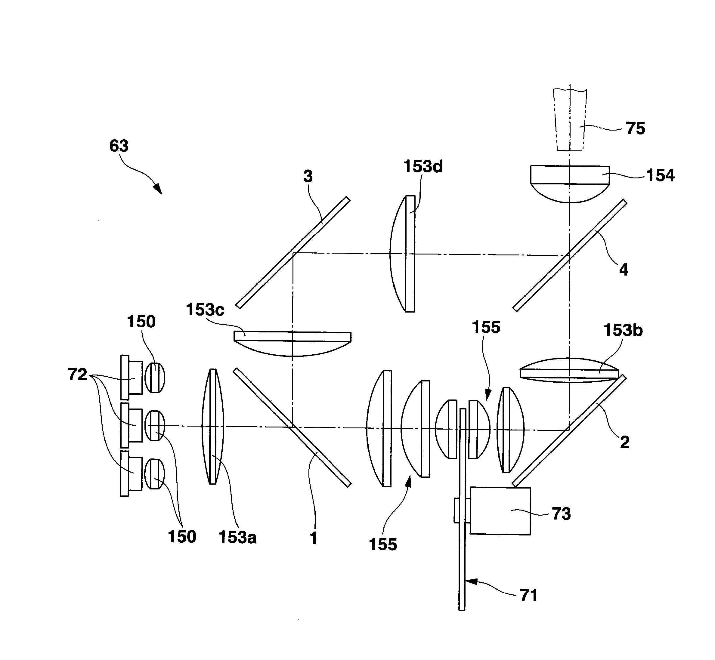
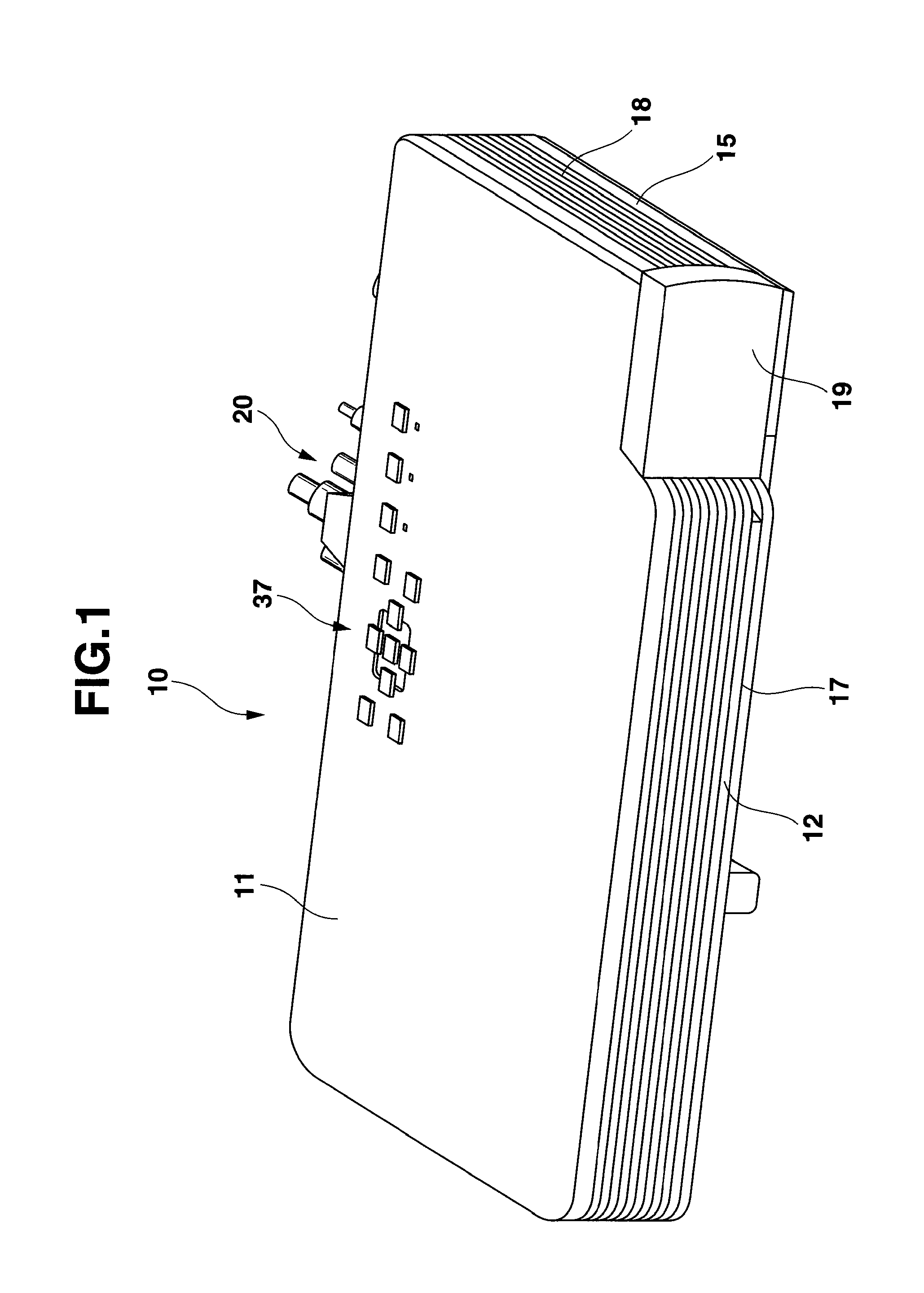
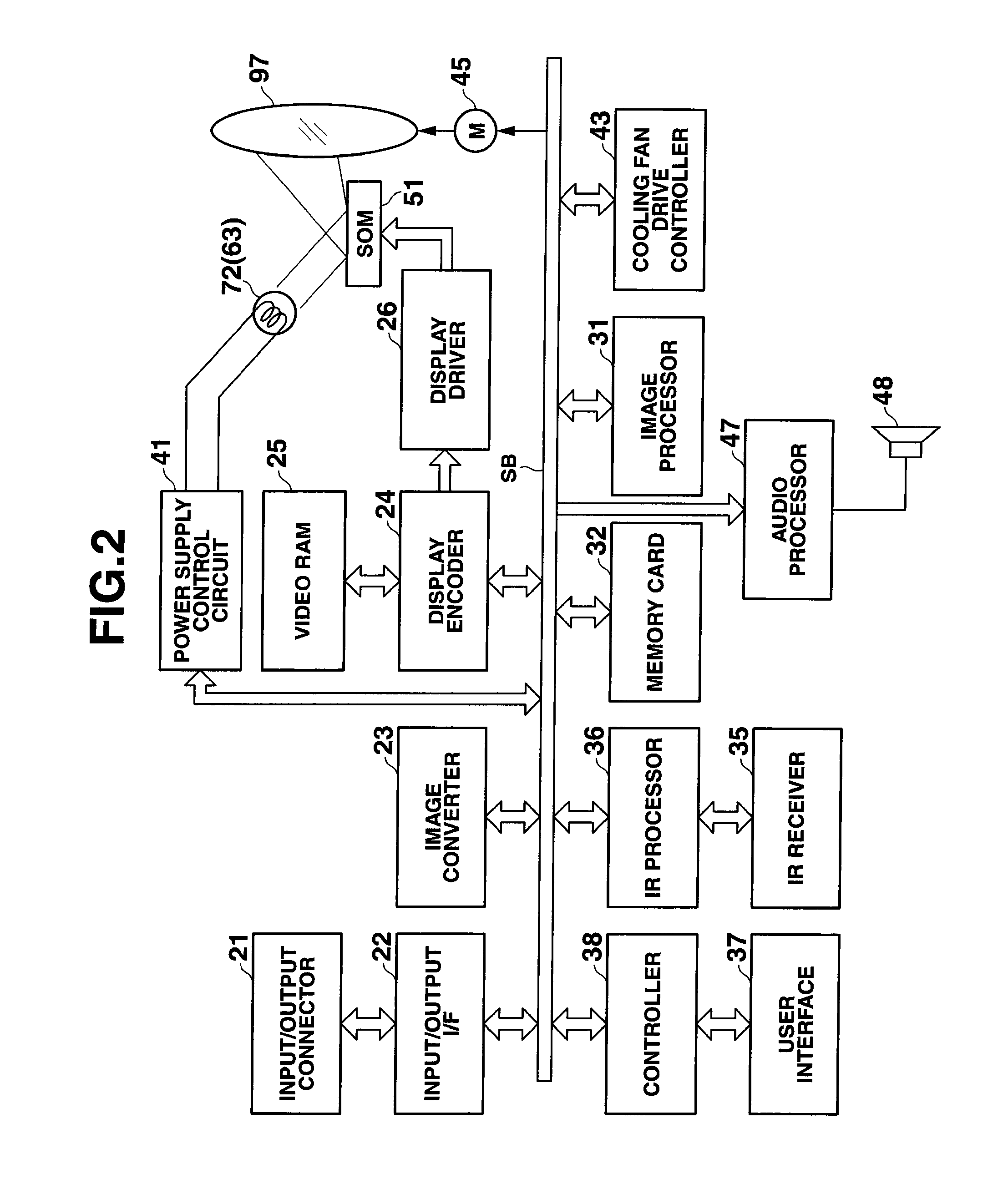
[0024]In the following description, a projector 10 will be described as an embodiment of the present invention. The projector 10 is provided with a light source device 63, a display element 51, a cooling fan, a source-side optical system 62, a projection-side optical system 90, and a projector control unit. The source-side optical system 62 guides light from the light source device 63 to the display element 51. The projection-side optical system 90 projects an image emitted from the display element 51 onto a screen. The projector control unit controls the light source device 63 and the display element 51.

[0025]The light source device 63 has a fluorescent wheel 71 which is a light emitting plate. The fluorescent wheel 71 has three fa...


PUM


Abstract

A light source device includes: a light emitting plate that has a plurality of segment regions including a transmissive portion that transmits light and a reflective portion on which a fluorescent substance layer; a light source that irradiates the fluorescent substance layer of the light emitting plate with the excitation light; a dichroic mirror that is disposed between the light source and the light emitting plate to transmit the excitation light and reflect fluorescent light from fluorescent substances of the fluorescent substance layer; and an optical device that condenses the excitation light transmitted by the transmissive portion of the light emitting plate and the fluorescent light reflected by the dichroic mirror on a single optical path to form a condensed light and radiate the condensed light toward the same direction.

Description

CROSS-REFERENCE TO THE RELATED APPLICATION(S)[0001]The present application is based upon and claims priority from prior Japanese Patent Application No. 2009-155434, filed on Jun. 30, 2009, the entire content of which are incorporated herein by reference.BACKGROUND[0002]1. Field of the Invention[0003]The present invention relates to a light source device and a projector including the light source device.[0004]2. Description of the Related Art[0005]Nowadays, data projectors are often used as image projection apparatuses for projecting a display image of a personal computer, a video image, an image based on image data stored in a memory card or the like onto a screen. In such a projector, light emitted from a light source is condensed on a micromirror display device called a DMD (Digital Micromirror Device) or a liquid crystal panel so as to display a color image on a screen.[0006]Conventionally, use of high-luminance discharge lamps as light sources in such projectors has become the m...

Claims


Application Information

Patent Timeline
IPC IPC(8): G03B21/28F21V9/16
CPCG03B21/204F21V9/16G03B21/28
Inventor KUROSAKI, HIDEYUKIINOUE, HIDEAKI
Owner CASIO COMPUTER CO LTD
Why Eureka
Try Eureka