Heat exchanger for esp motor

a technology of heat exchanger and motor, which is applied in the direction of non-positive displacement fluid engine, pump components, piston pumps, etc., can solve the problems of poor heat transfer, limited effect, and inability to absorb heat from the oil to the surrounding well fluid, so as to reduce the temperature of the motor oil and improve the efficiency of cooling the motor. , the effect of prolonging the life of the motor

Inactive Publication Date: 2010-12-30
BAKER HUGHES INC
View PDF23 Cites 32 Cited by
  • Summary
  • Abstract
  • Description
  • Claims
  • Application Information

AI Technical Summary

Benefits of technology

[0009]The heat exchanger arrangement reduces the temperature of the motor oil to thereby cool the motor more effectively. Thus, the life of the motor is advantageously extended and its reliability is advantageously increased.

Problems solved by technology

The internal oil has lubricant properties and in some way helps dissipate the heat from internals of the motor through heat transfer, but its effect is limited.
However, rejection of heat from the oil to the surrounding well fluid is usually limited due to the well fluid's high temperature, and also poor heat transfer characteristics due to high viscosity.
The increased temperature of the motor oil may lead to low performance or premature failure of the motor.

Method used


Image

  • Heat exchanger for esp motor
  • Heat exchanger for esp motor
  • Heat exchanger for esp motor

Examples


Embodiment Construction

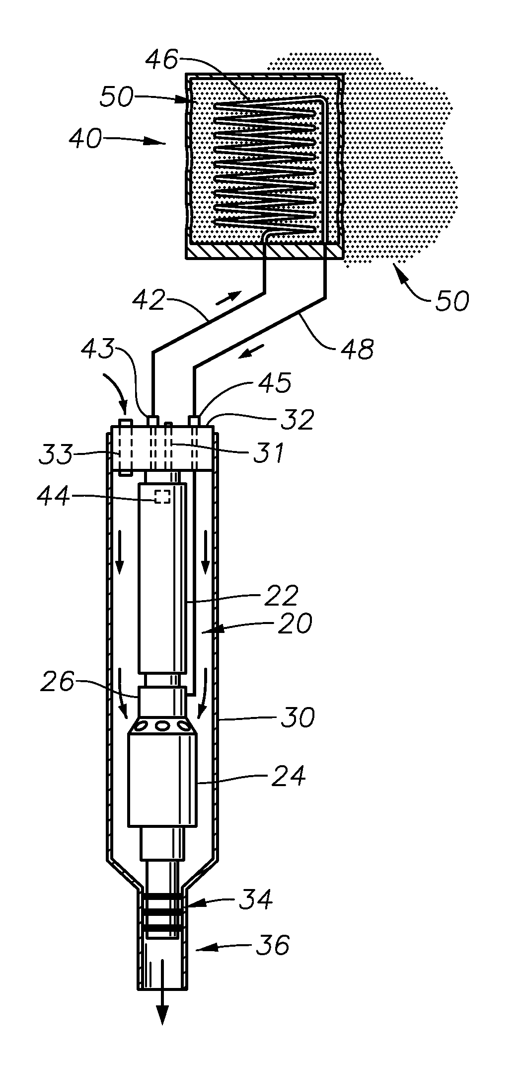
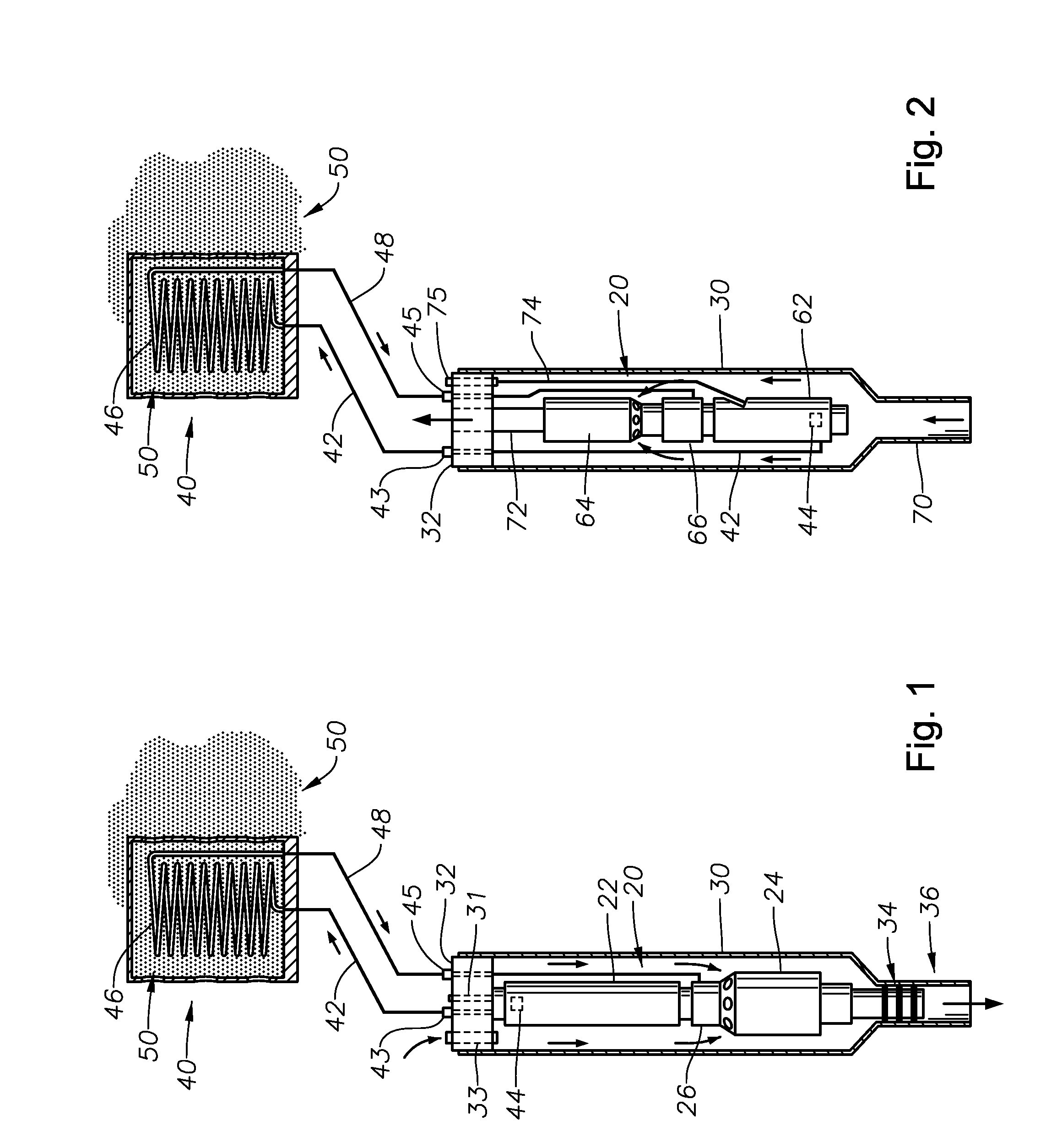
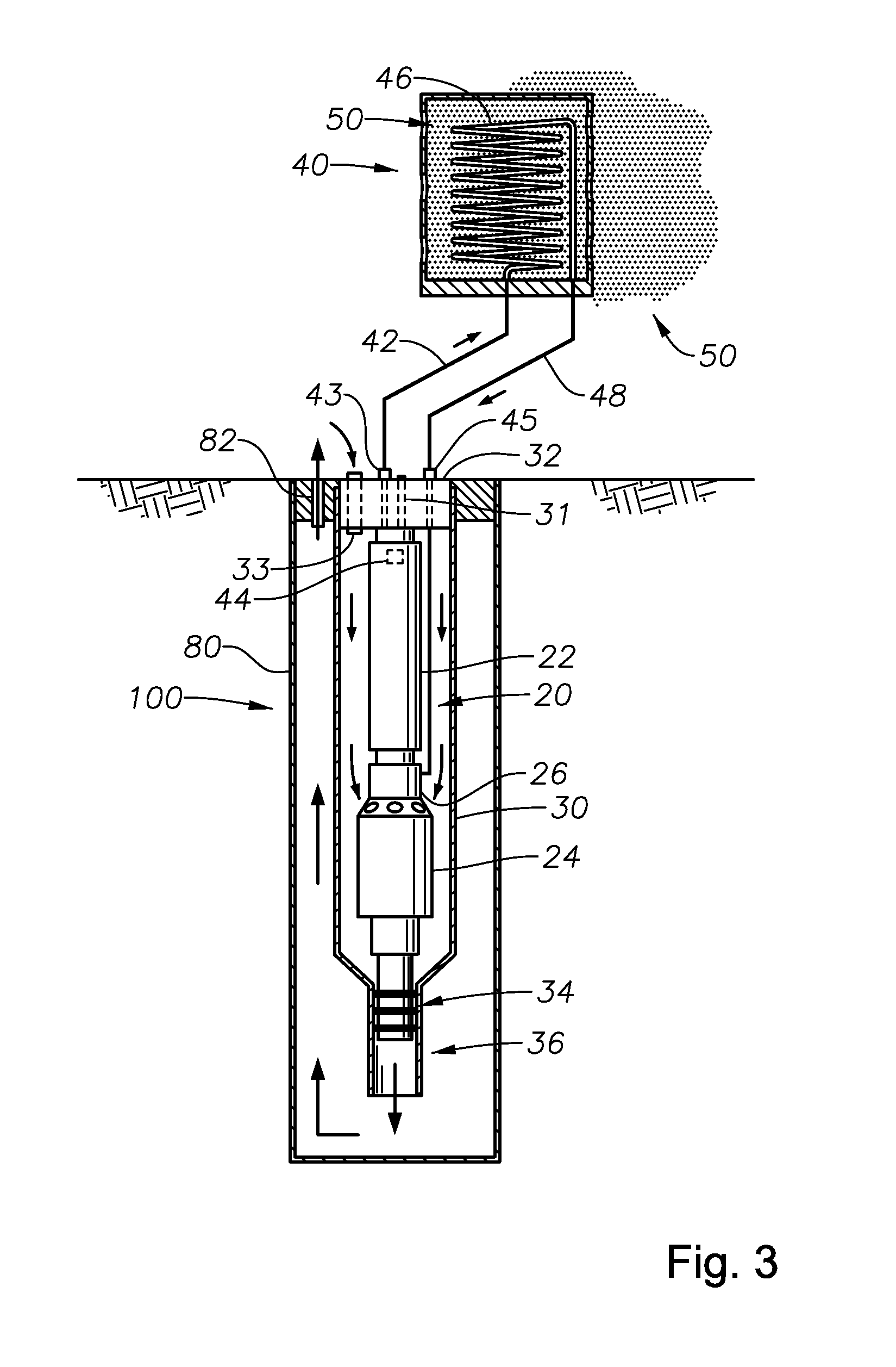
[0015]Referring to FIG. 1, an electrical submersible pump (“ESP”) 20 is illustrated in a sectional view. The ESP 20 can be part of a boosting system located on the seabed. It may be horizontally mounted, inclined, or vertically mounted with a caisson in the seafloor. A motor 22 and pump 24 are shown with a seal section 26 located in between. The seal section 26 contains a thrust bearing and a pressure equalizer to equalize the pressure of lubricant in the motor 22 with the hydrostatic pressure.

[0016]A capsule 30 houses the ESP 20 and has a cap or barrier 32 at one end and a discharge port 36 at the other end. Capsule 30 in this example is located on the sea floor and is horizontal or inclined on a skid. The cap 32 can have various types of ports and connections depending on the configuration of the ESP within the capsule 30. In this example, the motor 22 and pump 24 are in the inverted position such that the base of the motor 22 faces the end of the capsule 30 with the cap 32. A sta...


PUM


Abstract

A heat exchanger to serve ESP equipment installed on the seabed located in either a caisson or skid. A hot oil line connects the base of the ESP motor with the externally located heat exchanger, allowing hot motor oil to be circulated through coils externally exposed to seawater. The heat from the oil is rejected to the seawater and the cooled oil is reintroduced to the motor via a cold oil line that communicates with the seal section. The heat exchanger arrangement reduces the temperature of an ESP motor, thus allowing the motor to operate longer and more reliably.

Description

CROSS-REFERENCE TO RELATED APPLICATION[0001]This application claims priority to provisional application 61 / 221,451, filed Jun. 29, 2009, and is herein incorporated by reference in its entirety.FIELD OF THE INVENTION[0002]This invention relates in general to booster electric motors, and in particular to reducing the temperature of a sea floor submersible electric pump motor with a heat exchanger.BACKGROUND OF THE INVENTION[0003]Electrical submersible pumps (“ESP”) are used for pumping high volumes of well fluid, particularly in wells requiring artificial lift. The ESP typically has at least one electrical motor that normally is a three-phase, AC motor. The motor drives a centrifugal pump that may contain a plurality of stages, each stage comprising an impeller and a diffuser that increases the pressure of the well fluid. The motor is filled with a dielectric lubricant or oil that provides lubrication and aids in the removal of heat from the motor during operation of the ESP. A seal s...

Claims


Application Information

Patent Timeline
Patent Type & Authority Applications(United States)
IPC IPC(8): F04D29/58
CPCF04D29/588F04D13/10
Inventor MARTINEZ, IGNACIOMERRILL, DAN A.
Owner BAKER HUGHES INC
Why Eureka
Try Eureka