Dental Implant System

a technology of implant system and gingiva, applied in dentistry, medical science, dentistry preparations, etc., can solve the problems of loss of implant, inability of gingiva to fuse, and hinder proper oral hygiene, and achieve mechanically stable and long-lasting connection, good fusing

Inactive Publication Date: 2010-12-30
DENTAL SERVICE CENT MICHAEL MENZEL
View PDF13 Cites 11 Cited by
  • Summary
  • Abstract
  • Description
  • Claims
  • Application Information

AI Technical Summary

Benefits of technology

[0018]The goal of the invention is to overcome the disadvantages in the prior state of the art. In particular, the goal is to create an aesthetically appealing dental implant system which remains invisible at the gingival margin, enables good fusing with the gingiva in the gingival region, and guarantees a mechanically stable and long-lasting connection between a dental abutment and the jaw bone.

Problems solved by technology

Inherent to the design is the formation of a gap between the implant and the abutment, the gap being susceptible to bacteriological colonisation.
Because the pockets are not accessible to the patient himself, they require expensive and for the patient annoying dental recall measures to clean the affected pocket of bacteria and regularly also lead to loss of the implant.
Cleaning the pocket further results in the gingiva not being able to fuse with the abutment in the region above the gap between the abutment and the implant.
Furthermore, the temporarily unavoidable restricted accessibility of the periodontal pockets hinders proper oral hygiene in this region.
As a result, the patient considers the implant to be very unpleasant.
A further disadvantage is that the threaded connections between root implant and abutment are subjected to high mechanical loads.
As a result, micro-movements regularly occur between the implant and the abutment, which, in the long run, lead to breakages of the screw with resulting high costs.
If the threaded connection is fixed with cement or adhesive, moreover, cement or adhesive oozing from the connection may lead to irritation of the gingiva.
CE standards on the sterilization of medical articles do not permit the dentist performing the implantation to individually adapt the prefabricated implant during the implantation process.
It is a further disadvantage that the implant cannot be matched or adapted to bone dehiscences that arise when drilling the implant bed in the ridge-form jaw bone.
As a result, such implants have a significantly reduced bone contact area and, consequently, provide poorer anchoring, than would be possible with individual adaptation.
Furthermore, the anatomical soft-tissue demands of the gingiva are not taken into account.
Aesthetics and hygiene are thus greatly impaired.
Uncompensated bone dehiscences are regularly the cause of the formation of undesirable periodontal pockets.
Finally, high inventory costs are incurred, because the prefabricated standard implants must be kept in inventory in many sizes and forms.
The fixing of the superstructure to the abutment by means of an abutment post leads to unfavorable force distributions and lever ratios, resulting in turn in an increased risk of breakage.
Furthermore, it has been proven that thread-fastened abutment posts result in additional destructive micro-movements.
It is true that both solutions achieve a minimization of the gap, but it is foreseeable, that the contact between titanium, gold and gingiva, as well as saliva will trigger irritating chemical reactions.
The single component or integrated construction of the shaft and head section does indeed avoid a micro-gap in the enossal area, but it is still inevitable that a gap form between the shaft / head section and the abutment in the gingival region, the gap being susceptible to bacteriological colonisation.
Because the gingiva usually recedes over the course of time, it is unavoidable that, with time, the metallic abutment will protrude beyond the gingival margin and become visible.
Even so, these implants have not been able to assert themselves for several essential reasons.
This leads inevitably to mechanical loads on the implant during the period of fusing with the surrounding tissue and, consequently, frequently to failure of the implantation.
This is not acceptable from an aesthetic point of view, particularly when using titanium.
It is especially disadvantageous that the form of the implant does not take into consideration the vestibular / buccal and palatinal / lingual bone dehiscences that are caused by drilling into the ridge-form jaw bone.

Method used


Image

  • Dental Implant System
  • Dental Implant System
  • Dental Implant System

Examples


Embodiment Construction

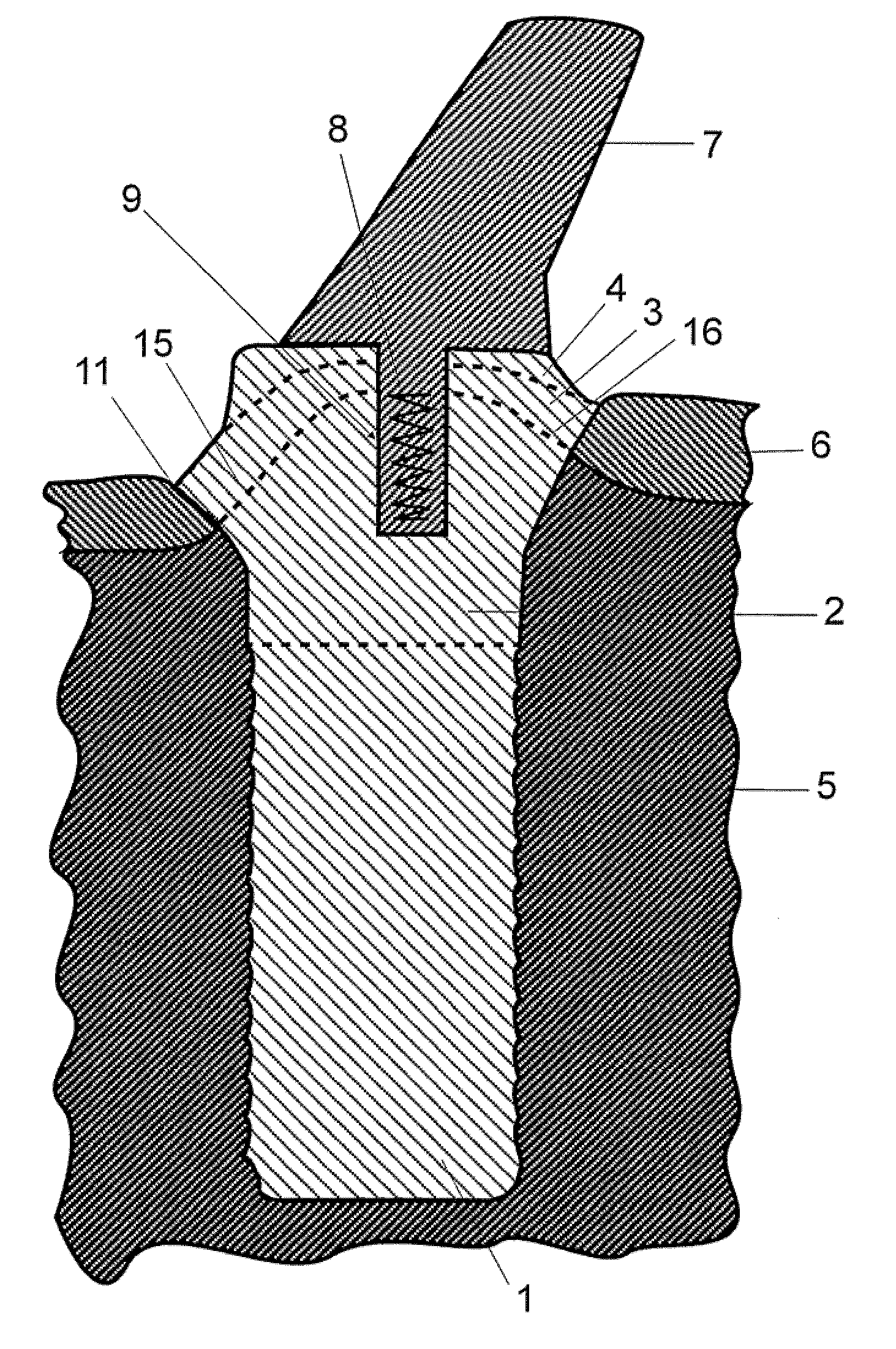
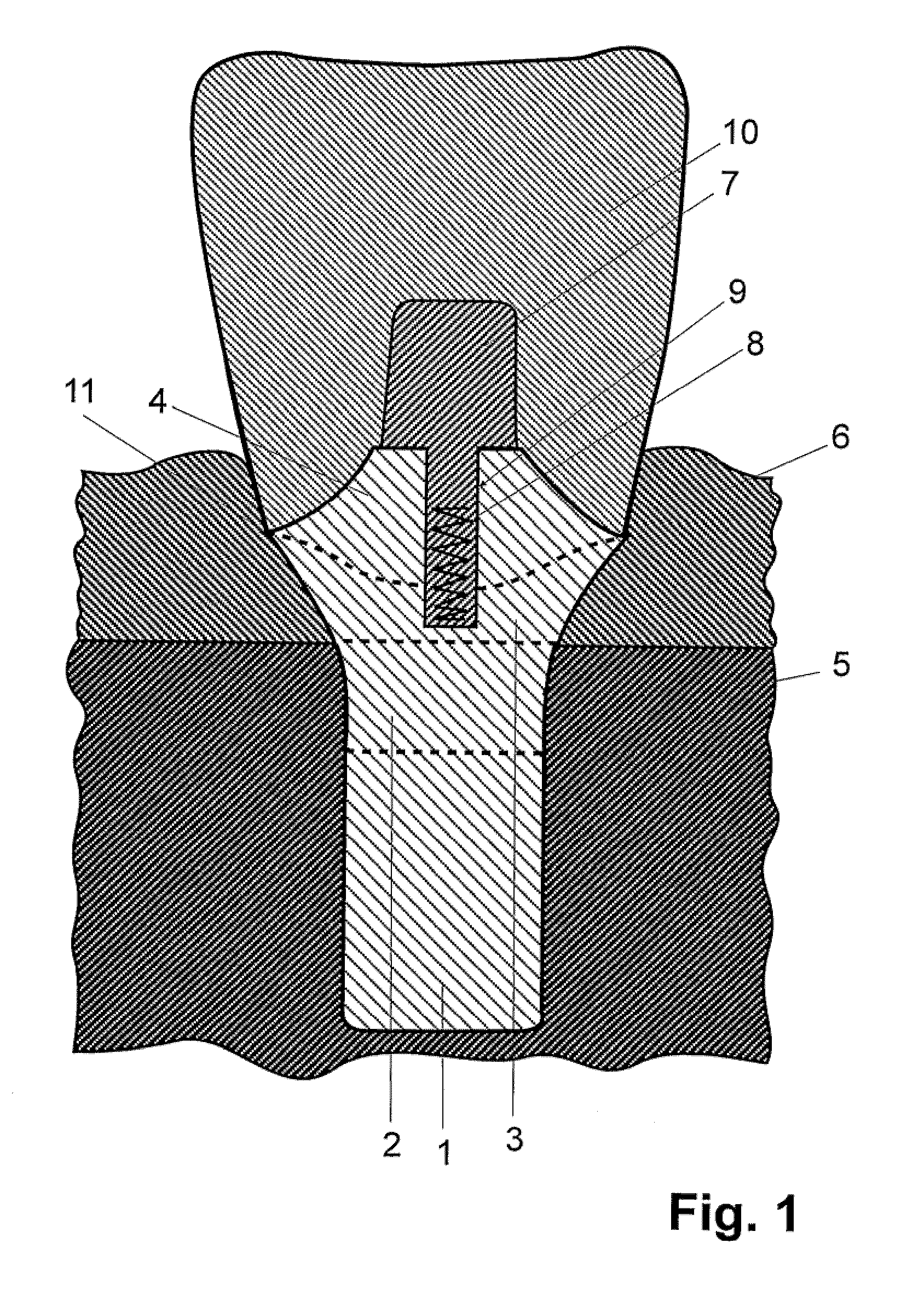
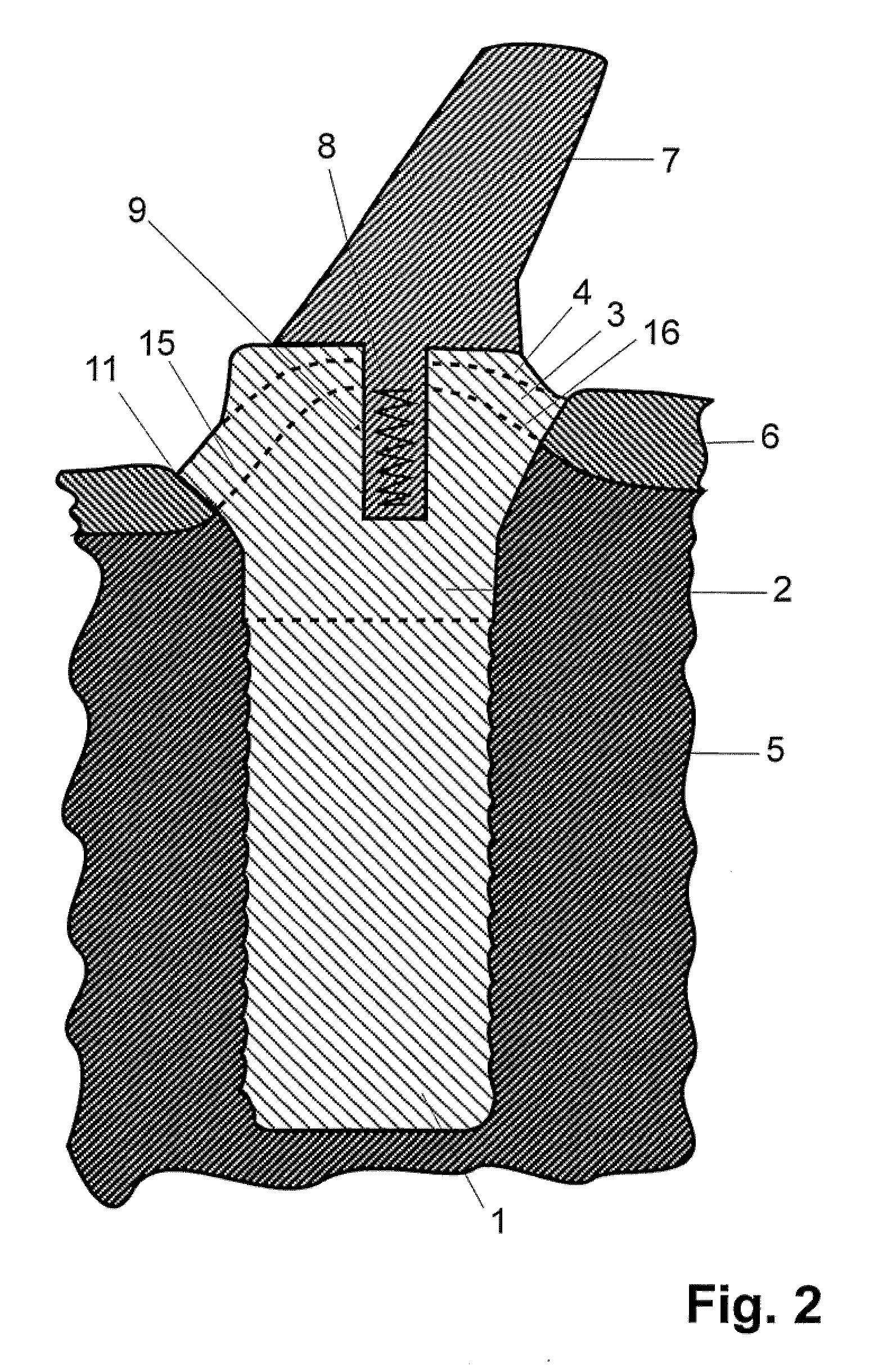
[0061]FIG. 1 shows the cross-section, viewed in the palatinal direction, of a one-piece dental implant 100 made of titanium, with a crown 10 fixed to the implant 100. For better illustration, FIG. 2 shows a cross-section of the implant 100 with a prosthetic mounting post 7, but viewed in the direction of the jaw bone.

[0062]The implant comprises a lower enossal section 1, an upper enossal section 2, a transgingival section 3 and a transgingival implant head 4. To manufacture the implant, section 1 and section 2 are formed by means of a CAD / CAM, and section 3 and the transgingival implant head 4 either by means of a CAD / CAM or by manual working of a blank.

[0063]The lower enossal section 1, which sits deep within the jaw bone, has a honeycomb structure on its surface, with protrusions in each of the corners of the honeycomb. This proven structure permits optimal fusing of the implant 100 into the bone.

[0064]The upper enossal section 2, which is shaped such that its upper edge aligns ex...


PUM


Abstract

Dental implant system for mounting a dental superstructure is disclosed. Enossal, gingival, transgingival sections plus implant head are integrated into a single-piece implant body. The enossal and gingival sections have geometries derived from diagnostic patient data and, thus, correspond geometrically precisely to the shape of the patient's jawbone and the drilled implant cavity and therefore completely fill those portions of the cavity. The superstructure covers the entire surface of the implant head, filling out the rest of the cavity. The surface structure of the dental implant has no gaps in it and portions of it are textured so as to facilitate complete fusing of tissue to implant, thereby preventing formation of gum pockets. Sections of the dental implant are rotationally asymmetrical, so as to ensure proper location of the implant in the cavity and prevent rotation. The construction of the implant also prevents the occurrence of micro-movements.

Description

FIELD OF THE INVENTION[0001]The invention refers to a dental implant system comprising an implant and a superstructure.BACKGROUND INFORMATIONDescription of the Prior Art[0002]Around 700,000 artificial tooth replacements are implanted each year in Germany. Usually, this replacement involves three components: an artificial root (root implant), a connecting piece, the so-called abutment, and a superstructure, such as a crown or bridge.[0003]In order to implant the artificial tooth replacement, it is first necessary to remove all remains of the defective tooth, for example, its roots. Subsequently, a hole is drilled into the jaw bone and possibly provided with a screw thread, prior to the root implant being driven or screwed into this hole. The implant thus usually takes the form of a cylinder or taper. After implantation into the jaw, the implant must be left to heal for three to six months, so that it fuses with the jaw bone. During this period, the implant must not be subjected to me...

Claims


Application Information

Patent Timeline
Patent Type & Authority Applications(United States)
IPC IPC(8): A61C8/00
CPCA61C8/0077A61C8/0018A61K6/818A61K6/84A61C8/005A61C8/0075
Inventor MENZEL, MICHAELROERUP, HENNINGARAPOGLOU, KONSTANTINOS
Owner DENTAL SERVICE CENT MICHAEL MENZEL
Why Eureka
Try Eureka