
Virtual machine system and control method thereof

a virtual machine and control method technology, applied in the field of virtual machine systems, can solve the problems of performance degradation, increase the quantity of semiconductors mounted on the cpu, and increase and achieve the effect of increasing the quantity of semiconductors mounted on the cpu and power dissipation

Inactive Publication Date: 2010-12-30
HITACHI LTD
View PDF21 Cites 14 Cited by
  • Summary
  • Abstract
  • Description
  • Claims
  • Application Information

AI Technical Summary

Benefits of technology

[0016]In the technique described in US2006 / 0294519A, the parent VMM operates when updating the child VMCS, resulting in performance degradation. Furthermore, also when the OS operation is resumed, processing of the parent VMM is needed, resulting in performance degradation. In the techniques described in U.S. Pat. No. 5,109,489 and US2007 / 0028238A, large-scale function expansion which is the same degree as that in the case where an assist function is newly introduced is required of the CPU. The large-scale function expansion increases the quantity of semiconductors mounted on the CPU and power dissipation.
[0020]According to the present invention, it is possible to provide a method for raising the speed of both the child VMCS update and the OS operation resumption while holding down the increase of the semiconductor quantity and power dissipation to the minimum.

Problems solved by technology

In the technique described in US2006 / 0294519A, the parent VMM operates when updating the child VMCS, resulting in performance degradation.
Furthermore, also when the OS operation is resumed, processing of the parent VMM is needed, resulting in performance degradation.
The large-scale function expansion increases the quantity of semiconductors mounted on the CPU and power dissipation.
As appreciated from the foregoing description, there is a fear that at least one of the problems, i.e., the increase of the semiconductor quantity and power dissipation, the performance degradation at the time of child VMCS update, and the performance degradation at the time of OS operation resumption will occur in the conventional techniques.

Method used


Image

  • Virtual machine system and control method thereof
  • Virtual machine system and control method thereof
  • Virtual machine system and control method thereof

Examples


first embodiment

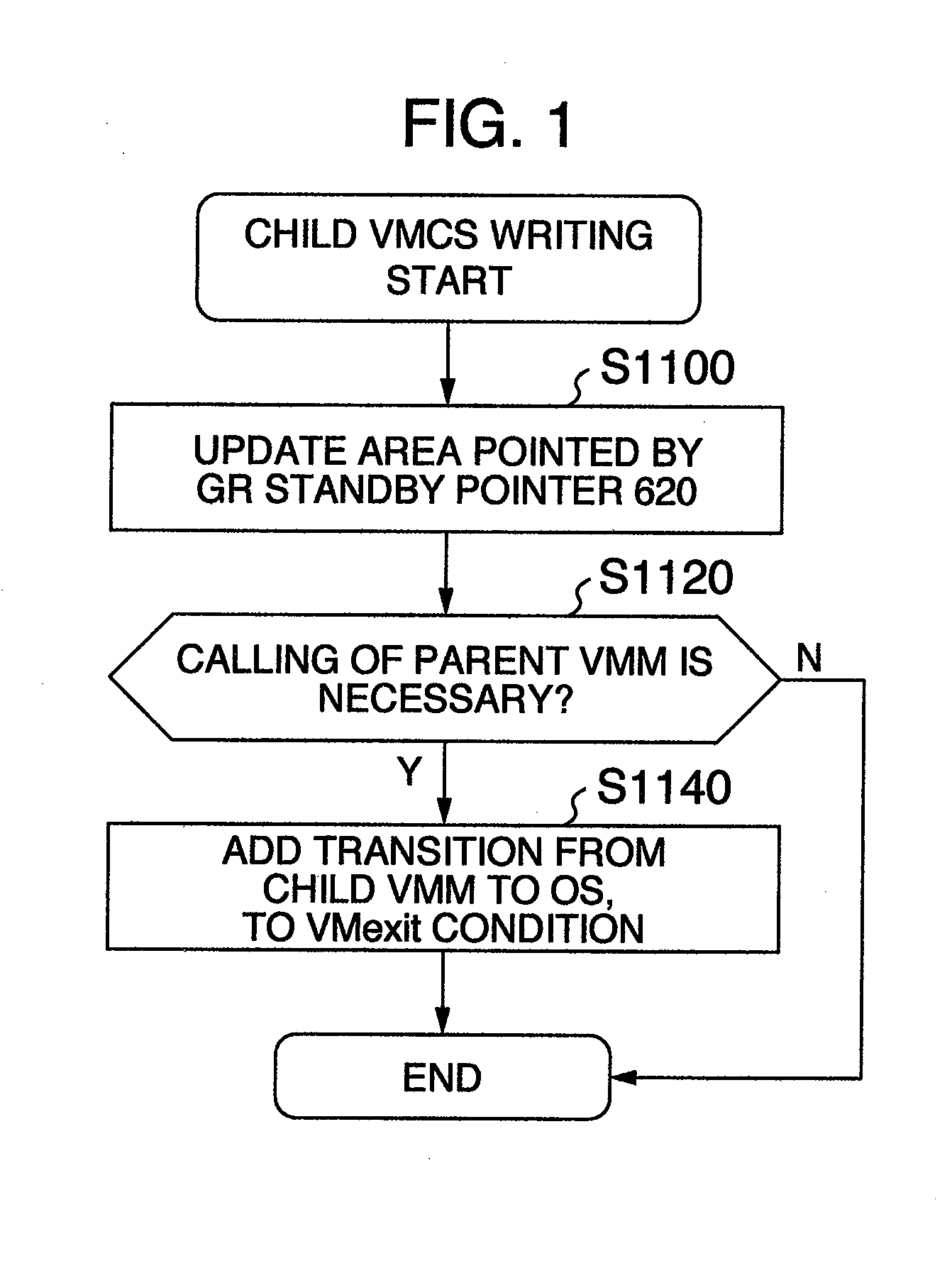
[0075]In the present embodiment, the child VMM is caused to utilize the VT function. Furthermore, the G field of the child VMCS is used as the G field of the parent VMCS for OS as well, and used as the common memory area. In the present embodiment, update of the child VMCS conducted by the child VMM is reflected to the parent VMCS for OS instantly or when the OS operation is resumed next time.

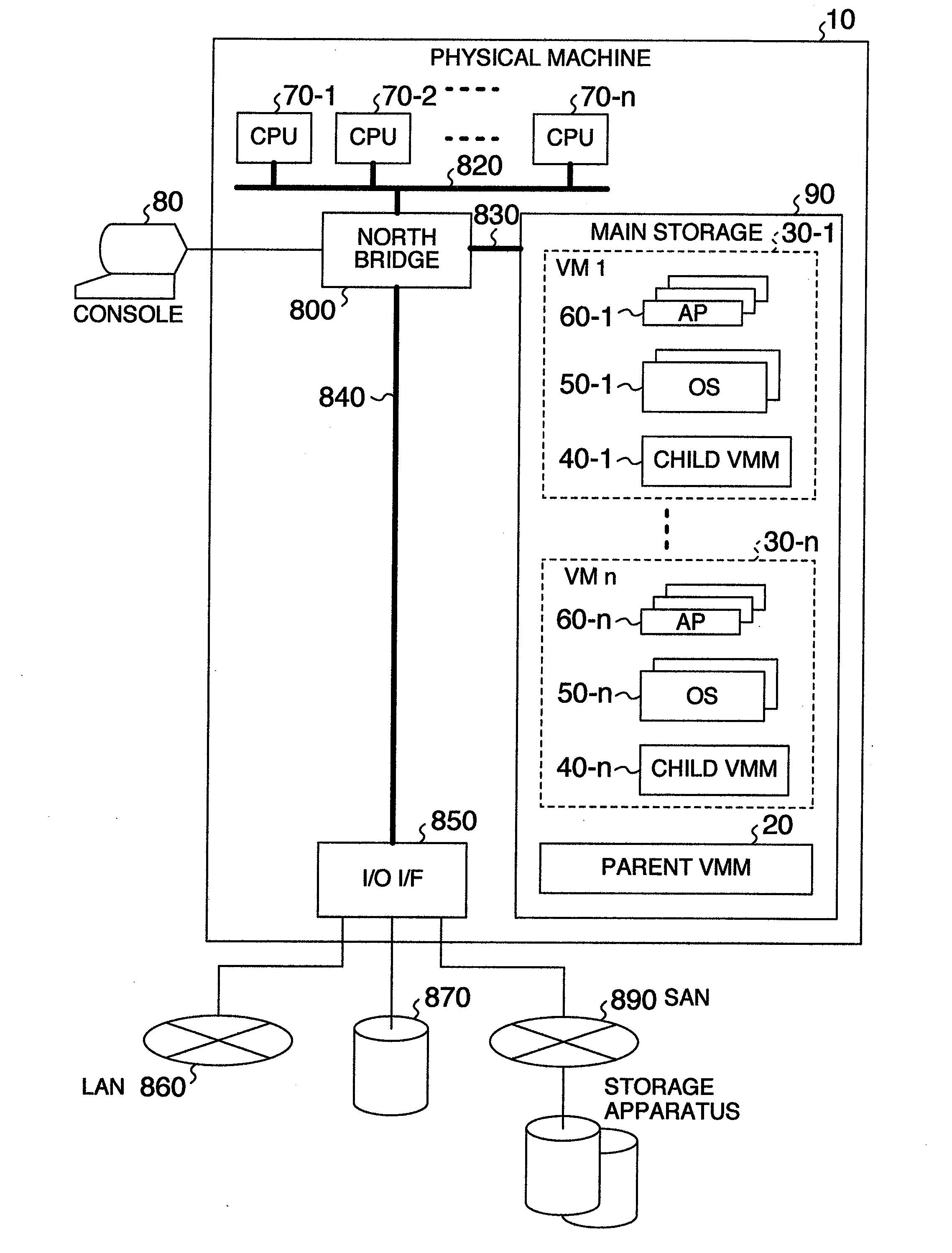
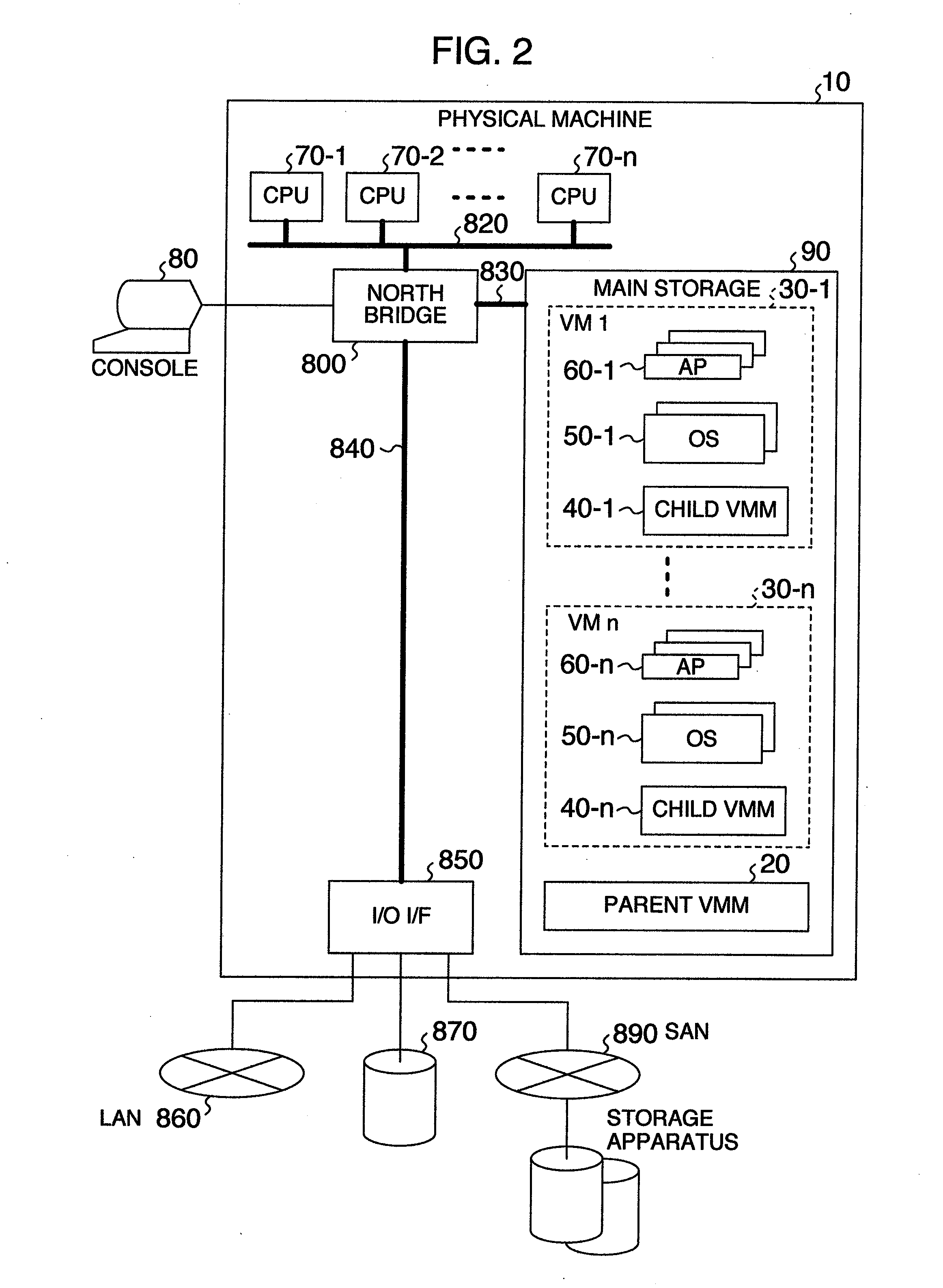
[0076]FIG. 2 shows a configuration of a physical machine which causes a two-level virtual machine system to operate in the first embodiment of the present invention.

[0077]The physical machine includes at least one CPU 70 corresponding to the VT function. These CPUs 70 are connected to a north bridge 800 (or a memory controller) via an inter-CPU interface 820 represented by a FSB (Front Side Bus).

[0078]A main storage 90 is connected to the north bridge 800 via a memory bus 830. Furthermore, an I / O device 850 is connected to the north bridge 800 via a bus 840. The I / O device 850 includes a networ...

second embodiment

[0181]Hereafter, an embodiment in which the child VMM is caused to utilize the VT function and the G field of the parent VMCS for OS is also used for the G field of the child VMCS, as a common memory area will be described. In the present embodiment, update of the child VMCS conducted by the child VMM is reflected to the parent VMCS for OS instantly. Furthermore, the R field of the parent VMCS for OS is also used for the R field of the child VMCS, as a common memory area. Hereafter, a difference from the first embodiment will be described with reference to accompanying drawings.

[0182]FIG. 2 shows a configuration of a physical machine which causes a two-level virtual machine system to operate in the second embodiment of the present invention. Since the configuration is the same as that in the first embodiment, its description will be omitted.

[0183]A principal part of a configuration of software which implements the virtual machine 30 on the physical machine 10 and hardware elements w...

third embodiment

[0267]Hereafter, an embodiment in which the child VMM is caused to utilize a SVM function and the G field of the child VMCB is also used for the G field of the parent VMCB for OS, as a common memory area will be described. In the present embodiment, update of the child VMCB conducted by the child VMM is reflected to the parent VMCB for OS instantly or when the OS operation is resumed next time. Hereafter, a difference from the first embodiment will be described with reference to accompanying drawings.

[0268]FIG. 2 shows a configuration of a physical machine which causes a two-level virtual machine system to operate in the third embodiment of the present invention. In the present embodiment, the physical machine 10 includes at least one CPU 70 corresponding to the SVM function. Remaining elements are the same as those in the first embodiment.

[0269]A principal part of a configuration of software which implements the virtual machine 30 on the physical machine 10 and hardware elements wh...


PUM


Abstract

In a two-level virtual machine system having child VMMs operating on a parent VMM, the field update frequency of VMCS and VMCB which control a VMM assist function of a CPU is not uniform. A G field requiring reflection of emulation results is higher in update frequency than a C field. The semiconductor quantity and power dissipation caused by the assist function expansion tend to increase in the C field used for a condition decision as compared with the G field simply retaining a value because influence upon the CPU operation is greater in the C field. Therefore, events relating to the G field which is high in update frequency and less in increase of semiconductor quantity and power dissipation caused by the assist function expansion are coped with by the CPU with its assist function expanded. Events relating to the C field are coped with by the parent VMM.

Description

INCORPORATION BY REFERENCE[0001]The present application claims priority from Japanese application JP2009-151738 filed on Jun. 26, 2009, the content of which is hereby incorporated by reference into this application.BACKGROUND OF THE INVENTION[0002]The present invention relates to a two-level virtual machine system in which a virtual machine (VM) is caused to operate on another virtual machine, and relates to a technique for emulating a virtualization support function of a CPU on a virtual machine with a low delay. In particular, the present invention relates to a method for improving the emulation performance of a virtualization support CPU in the two-level virtual machines.[0003]As the number of servers increases, complexity concerning the operation increases, and the operation cost poses a problem. As a technique for reducing the operation cost, therefore, server integration for putting together a plurality of servers into one is attracting attention. As a technique for implementi...

Claims


Application Information

Patent Timeline
Patent Type & Authority Applications(United States)
IPC IPC(8): G06F12/00G06F9/455
CPCG06F9/45558G06F2009/45566
Inventor OIWA, EIICHIROHATTORI, NAOYAMORIKI, TOSHIOMITSUSHIMA, YUJI
Owner HITACHI LTD
Learn More