
Underwater cutting device for the handle of MTR plate-type feul

a technology of plate-type fuel and cutting device, which is applied in the direction of metal sawing device, metal sawing apparatus, manufacturing tools, etc., can solve the problems of increasing operator radiation exposure, complicated process, and not smooth, so as to improve processing quality, reduce radiation exposure, and simplify the cutting process

Inactive Publication Date: 2011-01-06
INST NUCLEAR ENERGY RES ROCAEC
View PDF12 Cites 12 Cited by
  • Summary
  • Abstract
  • Description
  • Claims
  • Application Information

AI Technical Summary

Benefits of technology

[0007]The main objective for the invention is to provide an underwater cutting device for the handle of MTR plate-type fuel that is specially designed automation equipment for underwater cutting for the handle of MTR plate-type fuel. Therefore, it can effectively simplify the cutting process, increase efficiency, improve processing quality, absorb and filter cutting debris to keep the pond water clean, minimize operator radiation exposure, prevent contamination spreading and assure radiation protection and safety for operators.
[0008]Another objective for the invention is to provide an underwater cutting device for the handle of MTR plate-type fuel that uses automation to prevent dimensional error due to improper operation and assure the holding strength between the side plate and each fuel plate without the risk of being disassembled or damaged due to the absence of handles or other operation.

Problems solved by technology

Since it is not originally designed for the above-mentioned underwater cutting operation, in general, its process is complicated and not smooth.
It adds operational difficulty that not only affects efficiency but also increases operator radiation exposure.

Method used


Image

  • Underwater cutting device for the handle of MTR plate-type feul
  • Underwater cutting device for the handle of MTR plate-type feul
  • Underwater cutting device for the handle of MTR plate-type feul

Examples


Embodiment Construction

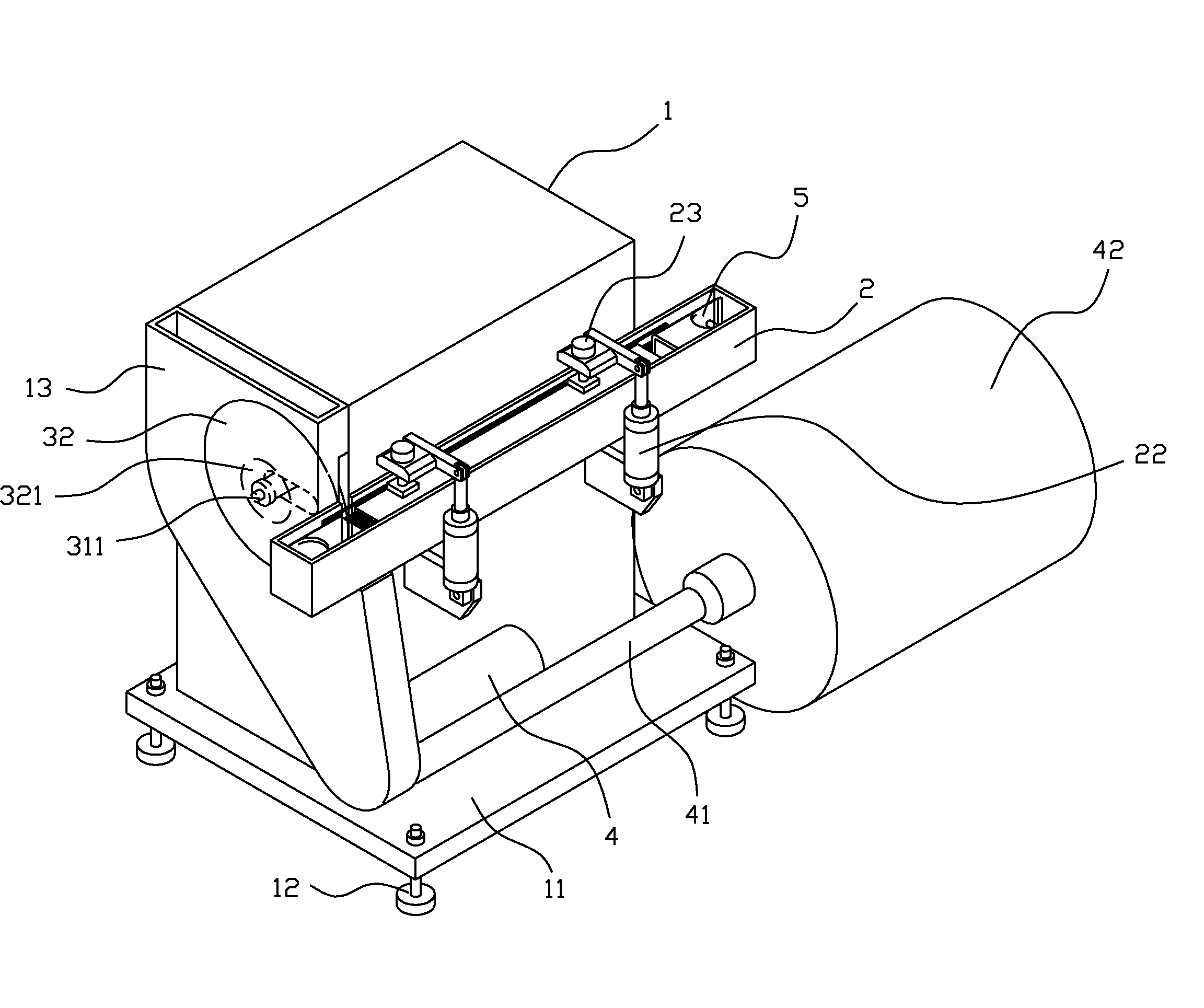
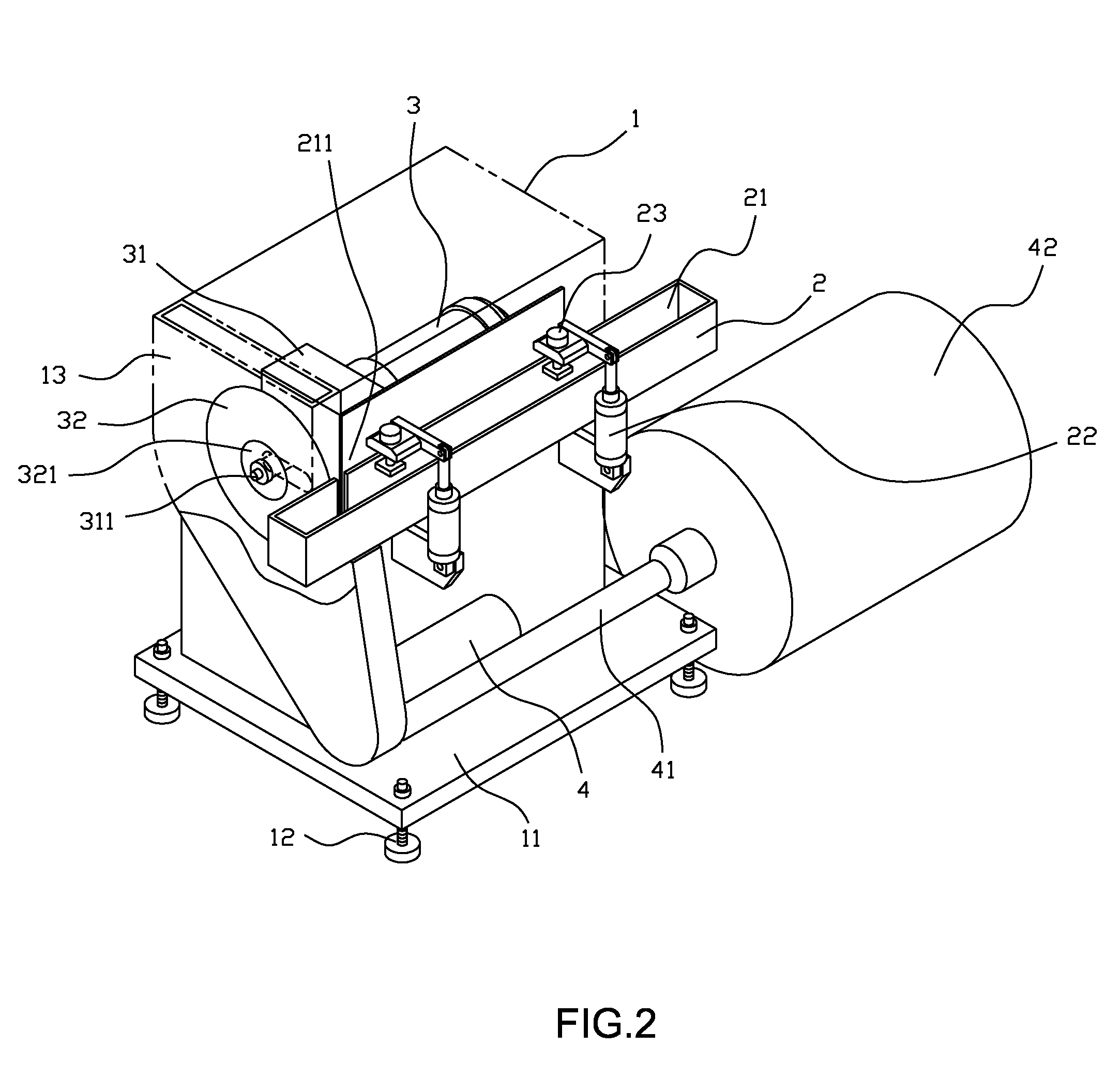
[0016]From FIG. 2 to FIG. 4, it can be clearly found that the structure for the invention mainly comprises: a housing 1, a positioning block 2, a primary motor 3 and a filtration motor 4. The housing 1 is located on a base 11 around which there are several height-adjustable feet 12. There is an accommodation space in the housing 1 in which there is a slidable base 14. There are several bearings 142 on the bottom of the slidable base 14 and they can be coupled with several lateral guide rods 141. Besides, between the inner walls of the slidable base 14 and the housing 1 there is a feed pneumatic cylinder 15. In front of the accommodation space, there is a cutting chamber 13. The positioning block 2 is located on the side with the housing 1 and contains a holding tank 21 that can accommodate MTR plate-type fuel 5. The holding tank 21 has an opening 211 on the side with the cutting chamber 13. Further, there is at least one positioning block pneumatic cylinder 22 on the side with the p...


PUM


Abstract

An underwater cutting device for the handle of MTR plate-type fuel has a housing that has an accommodation space for a feed pneumatic cylinder to drive a slidable base for lateral movement. And in front of the accommodation space there is a cutting chamber. A primary motor is located on the slidable base to drive the saw blade inside the cutting chamber to move and cut laterally with the slidable base that is driven by the feed pneumatic cylinder. A positioning block is located on the side with the housing and in the moving path of the saw blade. In the positioning block there is an accommodation space to hold the MTR plate-type fuel. Above the positioning block there is at least a pressing pneumatic cylinder to immobilize the MTR plate-type fuel and facilitate the saw blade to cut and remove the handle of MTR plate-type fuel. On the side of the bottom of the cutting chamber there is a filtration motor to absorb the metal cutting debris and deliver the debris through a conduit to the filter frame that contains filter for filtration.

Description

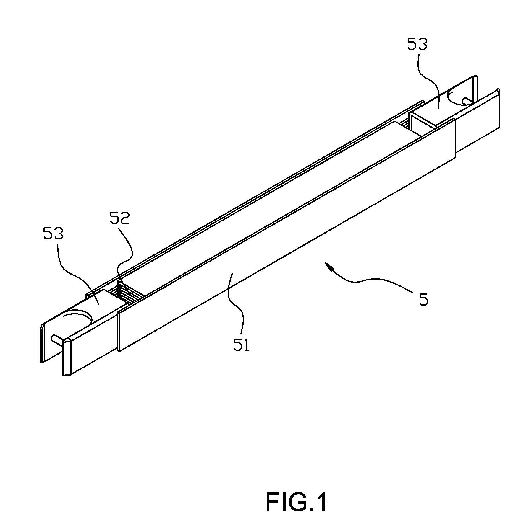
BACKGROUND OF THE INVENTION [0001]1. Field of the Invention[0002]The invention is related to the underwater cutting device for the handle of MTR (Material Test Reactor) plate-type fuel. Especially it refers to an underwater cutting device with a simplified cutting process, increased efficiency, improved processing quality, and ability to absorb and filter cutting debris to keep water clean, minimize operator radiation exposure, prevent contamination spreading and assure radiation protection and safety for operators.[0003]2. Description of the Prior Art[0004]MTR plate fuel is radioactive and the spent nuclear fuel rod is mainly stored in a water pond. The plate fuel structure is shown in FIG. 1 and mainly comprises: fuel plates, side plates and handles. Each set of MTR plate fuel is composed of 10 pieces fuel plates that are parallelly inserted into the side plate. The dimensions (including protective cover) for each fuel plate are 63.55 cm×7.05 cm×0.25 cm. The side plate is marked w...

Claims


Application Information

Patent Timeline
IPC IPC(8): B26D7/00B26D7/02B26D7/18
CPCB23D45/003Y10T29/531B23D57/0084B23D45/021Y10T83/263Y10T83/7493Y10T83/97
Inventor LEE, WEN-CHENCHIAO, LING-HUAN
Owner INST NUCLEAR ENERGY RES ROCAEC
Learn More